Cylinder Head -- Installation |
| 1. INSTALL EXHAUST MANIFOLD SUB-ASSEMBLY LH |
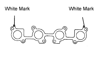
Place a new gasket on the cylinder head with the white mark facing the manifold side.
- NOTICE:
- Be careful of the installation direction.
 |
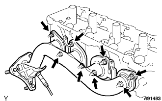
Install the exhaust manifold with 8 new nuts. Uniformly tighten the nuts in several passes.
- Torque:
- 44 N*m{449 kgf*cm, 32 ft.*lbf}
 |
| 2. INSTALL NO. 2 EXHAUST MANIFOLD HEAT INSULATOR |
Install the heat insulator with the 4 bolts.
- Torque:
- 7.5 N*m{76 kgf*cm, 66 in.*lbf}
| 3. INSTALL EXHAUST MANIFOLD SUB-ASSEMBLY RH |
Place a new gasket on the cylinder head with the white mark facing the manifold side.
- NOTICE:
- Be careful of the installation direction.
|
Install the exhaust manifold with 8 new nuts. Uniformly tighten the nuts in several passes.
- Torque:
- 44 N*m{449 kgf*cm, 32 ft.*lbf}
 |
| 4. INSTALL NO. 1 EXHAUST MANIFOLD HEAT INSULATOR |
Install the heat insulator with the 4 bolts.
- Torque:
- 7.5 N*m{76 kgf*cm, 66 in.*lbf}
| 5. INSTALL NO. 2 CYLINDER HEAD GASKET |
Place a new cylinder head gasket in position on the cylinder block.
- HINT:
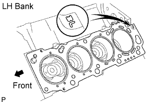
- The rear side of the cylinder head gasket has marks so that the RH and LH banks can be distinguished. A "3L" mark is on the LH bank's gasket.
- NOTICE:
- Be careful of the installation direction.
 |
| 6. INSTALL CYLINDER HEAD LH |
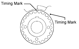
Check that the timing mark of the crankshaft timing pulley is in the position shown in the illustration, and that the piston is below the TDC of compression.
 |
Install the cylinder head together with the exhaust manifold to the cylinder block.
Apply a light coat of engine oil on the threads and under the head of the cylinder head bolts.
Put the washer on the bolt, and insert the bolt with washer into the cylinder head.
- NOTICE:
- Be careful not to drop washers into the cylinder head.
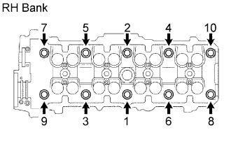
Install and uniformly tighten the 10 cylinder head bolts and plate washers in the sequence shown in the illustration.
- Torque:
- 59 N*m{601 kgf*cm, 44 ft.*lbf}
 |
Mark the front of the cylinder head bolt's head with paint.
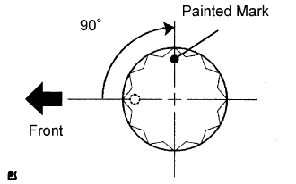 |
Tighten the cylinder head bolts another 90° in the sequence shown in the illustration.
Check that the painted mark is now at a 90° angle to the front.
| 7. INSTALL CYLINDER HEAD GASKET |
Place a new cylinder head gasket in position on the cylinder block.
- HINT:
- The rear side of the cylinder head gasket has marks so that the RH and LH banks can be distinguished. A "3R" mark is on the RH bank's gasket.
- NOTICE:
- Be careful of the installation direction.
 |
| 8. INSTALL CYLINDER HEAD SUB-ASSEMBLY |
Check that the timing mark of the crankshaft timing pulley is in the position shown in the illustration, and that the piston is below the TDC of compression.
|
Install the cylinder head together with the exhaust manifold to the cylinder block.
Apply a light coat of engine oil on the threads and under the head of the cylinder head bolts.
Put the washer on the bolt, and insert the bolt with washer into the cylinder head.
- NOTICE:
- Be careful not to drop washers into the cylinder head.
Install and uniformly tighten the 10 cylinder head bolts, and plate washers in the sequence shown in the illustration.
- Torque:
- 59 N*m{601 kgf*cm, 44 ft.*lbf}
 |
Mark the front of the cylinder head bolt's head with paint.
|
Tighten the cylinder head bolts another 90° in the sequence shown in the illustration.
Check that the painted mark is now at a 90° angle to the front.
| 9. INSTALL FRONT TWC |
Install 2 new gaskets to the 2 TWCs.
- NOTICE:
- Do not reuse the gaskets.
Install the 2 TWCs to the exhaust manifold with the 6 nuts.
- Torque:
- 62 N*m{632 kgf*cm, 46 ft.*lbf}
 |
| 10. INSTALL NO. 2 ENGINE HANGER |
Install the engine hanger with the 2 bolts.
- Torque:
- 37 N*m{377 kgf*cm, 27 ft.*lbf}
| 11. INSTALL NO. 1 ENGINE HANGER |
Install the engine hanger with the 2 bolts.
- Torque:
- 37 N*m{377 kgf*cm, 27 ft.*lbf}
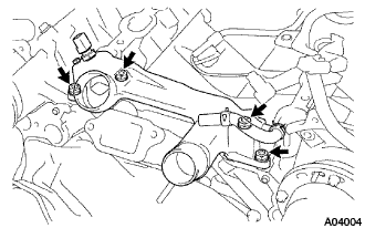
| 12. INSTALL FRONT WATER BY-PASS JOINT |
Install 2 new gaskets and the water by-pass joint with the 4 nuts. Alternately tighten the nuts.
- Torque:
- 18 N*m{184 kgf*cm, 13 ft.*lbf}
 |
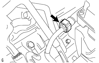
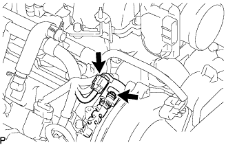
Connect the ECT connector.
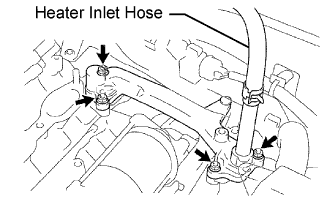
| 13. INSTALL WATER INLET HOUSING |
Install a new O-ring to the water inlet housing.
 |
Apply soapy water on the O-ring.
Apply seal packing to the sealing groove of the inlet housing as shown in the illustration.
- Seal packing:
- Part No. 08826-00100 or equivalent
- Seal diameter:
- 2 to 3 mm (0.08 to 0.12 in.)
- NOTICE:
- Remove any oil from the contact surface.
- Install the water inlet housing within 3 minutes after applying seal packing.
- Do not start the engine for at least 2 hours after installing it.
Install the water inlet and housing with the 2 bolts. Alternately tighten the bolts.
- Torque:
- 18 N*m{184 kgf*cm, 13 ft.*lbf}
| 14. INSTALL REAR WATER BY-PASS JOINT |
Install 2 new gaskets and the water by-pass joint with the 4 nuts. Alternately tighten the nuts.
- Torque:
- 18 N*m{184 kgf*cm, 13 ft.*lbf}
 |
| 15. INSTALL INTAKE MANIFOLD ASSEMBLY |
Install the manifold (Click here).
| 16. INSTALL NO. 2 FUEL PIPE SUB-ASSEMBLY |
Connect the connector of the fuel tube connected to the fuel main tube, then pinch the connector.
 |
| 17. INSTALL NO. 3 CAMSHAFT SUB-ASSEMBLY |
- NOTICE:
- Since the thrust clearance of the camshaft is small, the camshaft must be kept level while it is being installed. If the camshaft is not kept level, the portion of the cylinder head receiving the shaft thrust may crack or be damaged, causing the camshaft to seize or break. To avoid this, the following steps should be carried out.
Apply engine oil to the cam and gear of the camshaft and also the journal of the cylinder head.
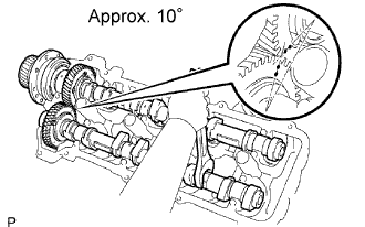 |
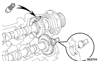
Align the timing marks (2 dot marks each) of the camshaft drive and driven main gears, and place the No. 3 and No. 4 camshafts.
Set the timing mark (2 dot marks each) of the camshaft drive and driven main gears at an angle of approximately 10°.
Apply seal packing to the camshaft housing plug.
- Remove the old packing (FIPG) material.
- Apply seal packing to the housing plug as shown in the illustration.
- Seal packing:
- Part No. 08826-00080 or equivalent
- Remove the old packing (FIPG) material.
 |
Install the camshaft housing plug to the cylinder head as shown in the illustration.
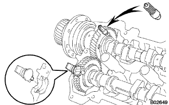 |
Install the oil control valve filter to the cylinder head.
- NOTICE:
- Be careful of the installation direction.
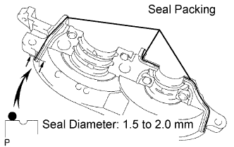
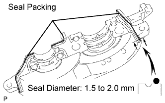
Apply seal packing to the front bearing cap.
- Remove any old packing (FIPG) material.
- Apply seal packing to the bearing cap as shown in the illustration.
- Seal packing:
- Part No. 08826-00080 or equivalent
- Seal diameter:
- 1.5 to 2.0 mm (0.059 to 0.079 in.)
- NOTICE:
- Do not apply seal packing to the front bearing cap grooves.
- Remove any old packing (FIPG) material.
 |
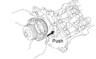
Install the front bearing cap.
- HINT:
- Installing the front bearing cap will determine the thrust portion of the camshaft.
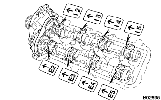 |
Install the other bearing caps in the sequence shown, with the arrow mark facing forward.
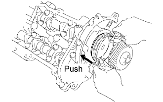
Push in the camshaft oil seal.
 |
Install 4 new seal washers to the bearing cap bolts (1 to 4).
 |
Apply a light coat of engine oil on the threads and under the heads of the bearing cap bolts (5 to 22).
- NOTICE:
- Do not apply engine oil under the heads of the bearing cap bolts (1 to 4).
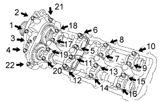
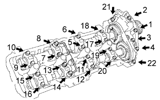
Install the oil feed pipe and the 22 bearing cap bolts.
Uniformly tighten the 22 bearing cap bolts in several passes in the sequence shown in the illustration.
- Torque:
- 7.5 N*m{76 kgf*cm, 66 ft.*lbf} for bolts 21 and 22
- 16 N*m{163 kgf*cm, 12 in.*lbf} for other bolts
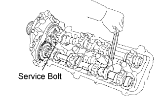
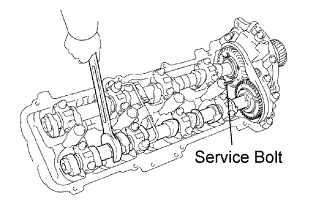
Remove the service bolt.
 |
| 18. INSTALL CAMSHAFT TIMING OIL CONTROL VALVE ASSEMBLY LH |
Install a new O-ring to the oil control valve.
 |
Install the oil control valve with the bolt.
- Torque:
- 7.5 N*m{76 kgf*cm, 66 in.*lbf}
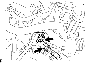
Connect the oil control valve connector.
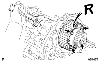
| 19. INSTALL CAMSHAFT TIMING PULLEY SUB-ASSEMBLY LH |
Align the camshaft timing tube knock pin with the knock pin groove of the timing pulley.
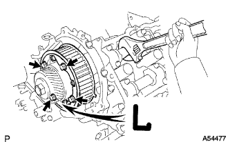 |
Attach the timing pulley to the camshaft timing tube. Face the timing pulley's "L" mark forward.
Hold the camshaft with a wrench and install the 4 pulley bolts.
- Torque:
- 7.5 N*m{76 kgf*cm, 66 in.*lbf}
| 20. INSTALL CAMSHAFT |
- NOTICE:
- Since the thrust clearance of the camshaft is small, the camshaft must be kept level while it is being installed. If the camshaft is not kept level, the portion of the cylinder head receiving the shaft thrust may crack or be damaged, causing the camshaft to seize or break. To avoid this, the following steps should be carried out.
Apply engine oil to the cam and gear of the camshaft and also the journal of the cylinder head.
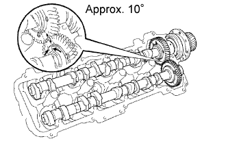 |
Align the timing marks (1 dot mark each) of the camshaft drive and driven main gears, and place the intake and exhaust camshafts.
Set the timing mark (1 dot mark each) of the camshaft drive and driven main gears at an angle of approximately 10°.
Apply seal packing to the camshaft housing plug.
- Remove the old packing (FIPG) material.
- Apply seal packing to the housing plug as shown in the illustration.
- Seal packing:
- Part No. 08826-00080 or equivalent
- Remove the old packing (FIPG) material.
|
Install the camshaft housing plug to the cylinder head as shown in the illustration.
 |
Install the oil control valve filter to the cylinder head.
- NOTICE:
- Be careful of the installation direction.
Apply seal packing to the front bearing cap.
- Remove any old packing (FIPG) material.
- Apply seal packing to the bearing cap as shown in the illustration.
- Seal packing:
- Part No. 08826-00080 or equivalent
- Seal diameter:
- 1.5 to 2.0 mm (0.059 to 0.079 in.)
- NOTICE:
- Do not apply seal packing to the front bearing cap grooves.
- Remove any old packing (FIPG) material.
 |
Install the front bearing cap.
- HINT:
- Installing the front bearing cap will determine the thrust portion of the camshaft.
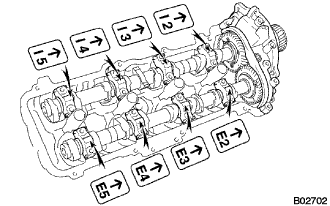 |
Install the other bearing caps in the sequence shown, with the arrow mark facing forward.
Push in the camshaft oil seal.
 |
Install 4 new seal washers to the bearing cap bolts (1 to 4).
 |
Apply a light coat of engine oil on the threads and under the heads of the bearing cap bolts (5 to 22).
- NOTICE:
- Do not apply engine oil under the heads of the bearing cap bolts (1 to 4).
Install the oil feed pipe and the 22 bearing cap bolts.
Uniformly tighten the 22 bearing cap bolts in several passes in the sequence shown in the illustration.
- Torque:
- 7.5 N*m{76 kgf*cm, 66 ft.*lbf} for bolts 21 and 22
- 16 N*m{163 kgf*cm, 12 in.*lbf} for other bolts
Remove the service bolt.
 |
| 21. INSTALL CAMSHAFT TIMING OIL CONTROL VALVE ASSEMBLY RH |
Install a new O-ring to the oil control valve.
 |
Install the oil control valve with the bolt.
- Torque:
- 7.5 N*m{76 kgf*cm, 66 in.*lbf}
Connect the oil control valve connector.
| 22. INSTALL REAR TIMING BELT PLATE RH |
Install the timing belt plate with the bolt and stud bolt.
- Torque:
- 7.5 N*m{76 kgf*cm, 66 in.*lbf}
| 23. INSTALL REAR NO. 2 TIMING BELT PLATE RH |
Install the timing belt plate with the 2 bolts.
- Torque:
- 7.5 N*m{76 kgf*cm, 66 in.*lbf}
| 24. INSTALL REAR TIMING BELT PLATE LH |
Install the timing belt plate with the bolt.
- Torque:
- 7.5 N*m{76 kgf*cm, 66 in.*lbf}
| 25. INSTALL REAR NO. 2 TIMING BELT PLATE LH |
Install the timing belt plate with the 2 bolts.
- Torque:
- 7.5 N*m{76 kgf*cm, 66 in.*lbf}
| 26. INSTALL CAMSHAFT TIMING PULLEY |
Align the camshaft timing tube knock pin with the knock pin groove of the timing pulley.
 |
Attach the timing pulley to the camshaft timing tube. Face the timing pulley's "R" mark forward.
Hold the camshaft with a wrench and install the 4 pulley bolts.
- Torque:
- 7.5 N*m{76 kgf*cm, 66 in.*lbf}
| 27. INSTALL CYLINDER HEAD COVER SUB-ASSEMBLY RH |
Remove any old packing (FIPG) material.
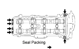 |
Apply seal packing to the cylinder heads as shown in the illustration.
- Seal packing:
- Part No. 08826-00080 or equivalent
- NOTICE:
- Remove any oil from the contact surface.
- Install the oil pan within 5 minutes after applying seal packing.
- Do not start the engine within 2 hours after applying seal packing.
Install the gasket to the cylinder head cover.
Install the seal washer to the bolt.
Install the cylinder head cover with the 9 bolts. Uniformly tighten the bolts in several passes.
- Torque:
- 6.0 N*m{61 kgf*cm, 53 in.*lbf}
Install the wire clamp bracket on the engine wire to the cylinder head.
Install the wire clamp bracket on the engine wire to the camshaft bearing cap.
| 28. INSTALL CYLINDER HEAD COVER SUB-ASSEMBLY LH |
Remove any old packing (FIPG) material.
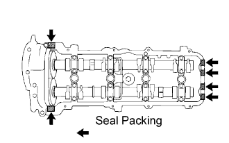 |
Apply seal packing to the cylinder heads as shown in the illustration.
- Seal packing:
- Part No. 08826-00080 or equivalent
- NOTICE:
- Remove any oil from the contact surface.
- Install the oil pan within 5 minutes after applying seal packing.
- Do not start the engine within 2 hours after applying seal packing.
Install the gasket to the cylinder head cover.
Install the seal washer to the bolt.
Install the cylinder head cover with the 9 bolts. Uniformly tighten the bolts in several passes.
- Torque:
- 6.0 N*m{61 kgf*cm, 53 in.*lbf}
Install the wire clamp bracket on the engine wire to the cylinder head.
Install the wire clamp bracket on the engine wire to the camshaft bearing cap.
| 29. INSTALL IGNITION COIL |
- Torque:
- 7.5 N*m{76 kgf*cm, 66 in.*lbf}
| 30. INSTALL TIMING BELT |
Install the timing belt (Click here).
| 31. CONNECT CABLE TO BATTERY NEGATIVE TERMINAL |
| 32. PERFORM INITIALIZATION |
Perform initialization (Click here).
- NOTICE:
- Certain systems need to be initialized after disconnecting and reconnecting the cable from the negative (-) battery terminal.