Engine Unit -- Inspection |
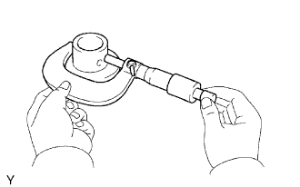
| 1. INSPECT VALVE LASH ADJUSTER ASSEMBLY |
 |
- NOTICE:
- Keep the lash adjuster free from dirt and foreign objects.
- Only use clean engine oil.
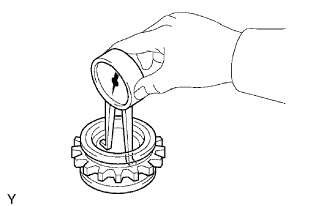
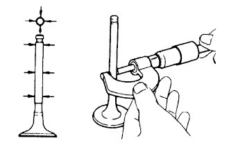
Place the lash adjuster into a container full of engine oil.
Insert SST's tip into the lash adjuster's plunger and use the tip to press down on the check ball inside the plunger.
- SST
- 09276-75010
Squeeze the SST and lash adjuster together to move the plunger up and down 5 to 6 times.
Check the movement of the plunger and bleed the air.
- OK:
- Plunger moves up and down.
- NOTICE:
- When bleeding high-pressure air from the compression chamber, make sure that the tip of the SST is actually pressing the check ball as shown in the illustration. If the check ball is not pressed, air will not bleed.
After bleeding the air, remove SST. Then try to quickly and firmly press the plunger with a finger.
- OK:
- Plunger is very difficult to move.
| 2. INSPECT CAMSHAFT |
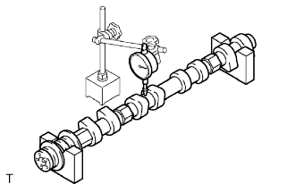 |
Inspect the camshaft for runout.
Place the camshaft on V-blocks.
Using a dial indicator, measure the circle runout at the center journal.
- Maximum circle runout:
- 0.04 mm (0.0016 in.)
- HINT:
- Check the oil clearance after replacing the camshaft.
Using a micrometer, measure the cam lobe height.
- Standard cam lobe height:
Item Specification Intake camshaft 43.950 to 44.050 mm (1.7303 to 1.7342 in.) Exhaust camshaft 44.110 to 44.210 mm (1.7366 to 1.74.5 in.)
 |
Using a micrometer, measure the journal diameter.
- Standard journal diameter:
Item Specification No. 1 journal 35.946 to 35.960 mm (1.4152 to 1.4157 in.) Other journal 25.959 to 25. 975 mm (1.0220 to 1.0226 in.)
 |
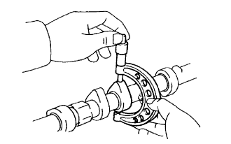
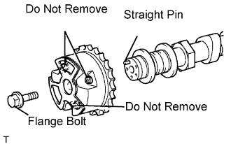
| 3. INSPECT CAMSHAFT TIMING GEAR ASSEMBLY |
Clamp the camshaft in a vise.
- NOTICE:
- Be careful not to damage the camshaft in the vise.
Put the camshaft timing gear and camshaft together by aligning the key groove and straight pin.
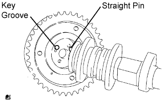 |
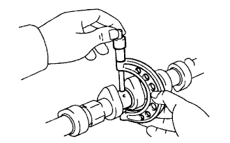
Lightly press the gear against the camshaft, and turn the gear. Push further at the position where the pin enters the groove.
- NOTICE:
- Be sure not to turn the camshaft timing gear in the retard direction (the right angle).
Check that there is no clearance between the gear's flange and the camshaft.
Tighten the flange bolt with the camshaft timing gear fixed.
- Torque:
- 100 N*m{1,020 kgf*cm, 74 ft.*lbf}
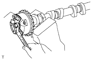 |
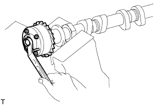
Check the lock of the camshaft timing gear.
Clamp the camshaft in a vise, and confirm that the camshaft timing gear is locked.
- NOTICE:
- Be careful not to damage the camshaft.
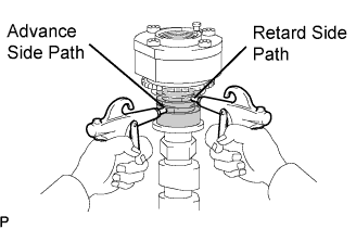
Release the lock pin.
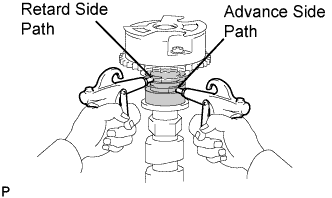
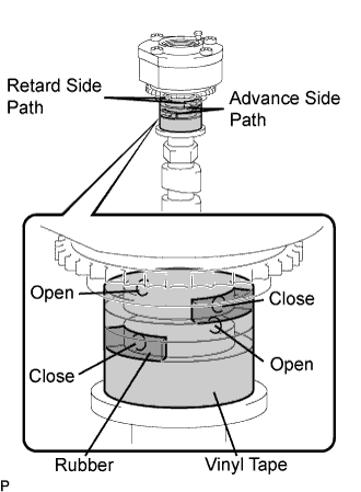
Cover the 4 oil paths of the cam journal with vinyl tape as shown in the illustration.
- HINT:
- 2 advance side paths are provided in the groove of the camshaft. Plug one of the paths with a rubber piece.
Break through the tape of the advance side path and the retard side path on the opposite side to the hole of the advance side path, as shown in the illustration.
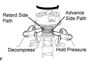
Apply approximately 200 kPa (2.0 kgf/cm2, 28 psi) of air pressure to the two broken paths.
- CAUTION:
- Cover the paths with a piece of cloth when applying pressure to keep oil from splashing.
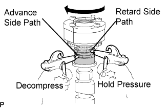
Check that the camshaft timing gear revolves in the advance direction when reducing the air pressure applied to the retard side path.
- HINT:
- This operation releases the lock pin for the most retarded position.
When the camshaft timing gear reaches the most advanced position, release the air pressure from the retard side path and advance side path, in that order.
- NOTICE:
- Do not release the air pressure from the advance side path first. The gear may abruptly shift in the retard direction and break the lock pin.
 |
Check for smooth rotation.
Turn the camshaft timing gear within its movable range (21°) 2 or 3 times, but do not turn it to the most retarded position. Make sure that the gear turns smoothly.
- NOTICE:
- Do not use air pressure to perform the smooth operation check.
Check the lock in the most retarded position.
Confirm that the camshaft timing gear is locked at the most retarded position.
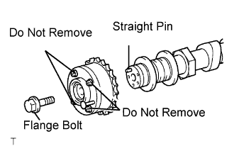
Remove the flange bolt and camshaft timing gear.
- NOTICE:
- Do not remove the other 3 bolts.
- If planning to reuse the gear, be sure to release the straight pin lock before installing the gear.
 |
| 4. INSPECT CAMSHAFT TIMING EXHAUST GEAR ASSEMBLY |
Clamp the camshaft in a vise.
- NOTICE:
- Be careful not to damage the camshaft in the vise.
Put the camshaft timing exhaust gear and camshaft together by aligning the key groove and straight pin.
|
Lightly press the gear against the camshaft, and turn the gear. Push further at the position where the pin enters the groove.
- NOTICE:
- Be sure not to turn the camshaft timing exhaust gear in the retard direction (the right angle).
Check that there is no clearance between the gear's flange and the camshaft.
Tighten the flange bolt with the camshaft timing exhaust gear fixed.
- Torque:
- 100 N*m{1,020 kgf*cm, 74 ft.*lbf}
 |
Check the camshaft timing exhaust gear lock.
Make sure that the camshaft timing exhaust gear is locked.
Release the lock pin.
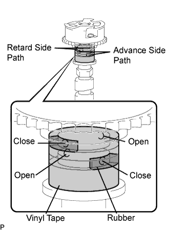
Cover the 4 oil paths of the cam journal with vinyl tape as shown in the illustration.
- HINT:
- 4 oil paths are provided in the groove. Plug 2 paths with rubber pieces.
Prick a hole in the tape placed on the advance side path. Prick a hole in the tape placed on the retard side path, on the opposite side to that of the advance side path, as shown in the illustration.
Apply approximately 200 kPa (2.0 kgf/cm2, 28 psi) of air pressure to the two broken paths (the advance side path and the retard side path).
- CAUTION:
- Cover the paths with a piece of cloth when applying pressure to keep oil from splashing.
Make sure that the camshaft timing exhaust gear turns in the retard direction when reducing the air pressure applied to the advance side path.
- HINT:
- The lock pin is released and the camshaft timing exhaust gear turns in the retard direction.
When the camshaft timing exhaust gear moves to the most retarded position, release the air pressure from the advance side path, and then release the air pressure from the retard side path.
- NOTICE:
- Be sure to release the air pressure from the advance side path first. If the air pressure of the retard side path is released first, the camshaft timing exhaust gear may abruptly shift in the advance direction and break the lock pin or other parts.
 |
Check for smooth rotation.
Turn the camshaft timing exhaust gear within its movable range (18.5°) 2 or 3 times, but do not turn it to the most advanced position. Make sure that the gear turns smoothly.
- NOTICE:
- When the air pressure is released from the advance side path and then from the retard side path, the gear automatically returns to the most advanced position due to the advance assist spring operation and locks. Gradually release the air pressure from the retard side path before performing the smooth rotation check.
Check the lock at the most advanced position.
Make sure that the camshaft timing exhaust gear is locked at the most advanced position.
Remove the flange bolt and camshaft timing exhaust gear.
- NOTICE:
- Be sure not to remove the other 3 bolts.
- If planning to reuse the gear, be sure to release the straight pin lock before installing the gear.
 |
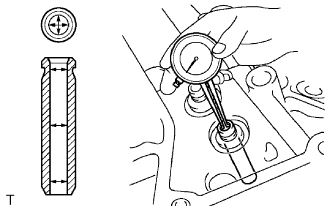
| 5. INSPECT CYLINDER HEAD SET BOLT |
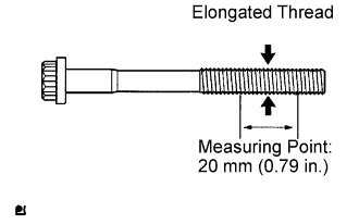 |
Using vernier calipers, measure the minimum diameter of the elongated thread at the measuring point.
- Standard outside diameter:
- 10.85 to 11.00 mm (0.4272 to 0.4331 in.)
- Minimum outside diameter:
- 10.70 mm (0.4213 in.)
- HINT:
- If a visual check reveals no excessively thin areas, check the center of the bolt and find the area that has the lowest diameter.
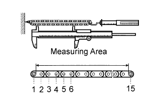
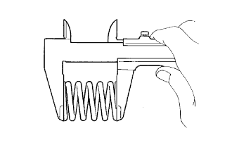
| 6. INSPECT CHAIN SUB-ASSEMBLY |
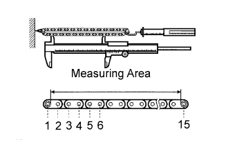 |
Pull the chain with a force of 147 N (15 kgf, 33 lbf) as shown in the illustration.
Using vernier calipers, measure the length of 15 links.
- Maximum chain elongation:
- 136.9 mm (5.390 in.)
- NOTICE:
- Perform the measurement at 3 random places. Inspect using the average of the measurements.
| 7. INSPECT NO.2 CHAIN SUB-ASSEMBLY |
 |
Pull the chain with a force of 147 N (15 kgf, 33 lbf) as shown in the illustration.
Using vernier calipers, measure the length of 15 links.
- Maximum chain elongation:
- 137.6 mm (5.417 in.)
- NOTICE:
- Perform the measurement at 3 random places. Inspect using the average of the measurements.
| 8. INSPECT CRANKSHAFT TIMING GEAR OR SPROCKET |
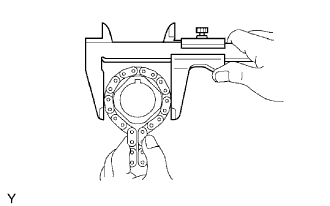 |
Wrap the chain around the sprocket.
Using vernier calipers, measure the sprocket diameter with the chain.
- Minimum sprocket diameter (with chain):
- 61.4 mm (2.417 in.)
- HINT:
- The vernier calipers must contact the chain rollers for the measurement.
| 9. INSPECT IDLE SPROCKET ASSEMBLY |
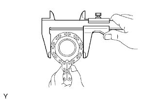 |
Wrap the chain around the sprocket.
Using vernier calipers, measure the sprocket diameter with the chain.
- Minimum sprocket diameter (with chain):
- 61.4 mm (2.417 in.)
- HINT:
- The vernier calipers must contact the chain rollers for the measurement.
| 10. INSPECT IDLE GEAR SHAFT OIL CLEARANCE |
 |
Using a micrometer, measure the idle gear shaft diameter.
- Idle gear shaft diameter:
- 30.000 to 30.013 mm (1.1811 to 1.1816 in.)
Using a caliper gauge, measure the inside diameter of the idle gear.
- Idle gear inside diameter:
- 30.020 to 30.033 mm (1.1819 to 1.1824 in.)
 |
Subtract the idle gear shaft diameter measurement from the idle gear inside diameter measurement.
- Standard oil clearance:
- 0.007 to 0.033 mm (0.0003 to 0.0013 in.)
- Maximum oil clearance:
- 0.083 mm (0.0033 in.)
| 11. INSPECT NO. 1 CHAIN TENSIONER ASSEMBLY |
 |
Move the stopper plate upward to release the lock. Push the plunger and check that it moves smoothly.
If necessary, replace the chain tensioner assembly.
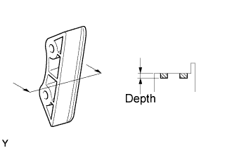
| 12. INSPECT NO. 2 CHAIN TENSIONER ASSEMBLY |
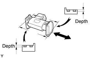 |
Check that the plunger moves smoothly.
Measure the worn depth of the chain tensioner.
- Maximum depth:
- 0.9 mm (0.035 in.)
| 13. INSPECT NO. 3 CHAIN TENSIONER ASSEMBLY |
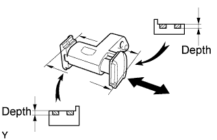 |
Check that the plunger moves smoothly.
Measure the worn depth of the chain tensioner.
- Maximum depth:
- 0.9 mm (0.035 in.)
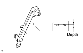
| 14. INSPECT CHAIN TENSIONER SLIPPER |
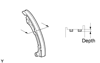 |
Measure the worn depth of the chain tensioner slipper.
- Maximum depth:
- 1.0 mm (0.039 in.)
| 15. INSPECT NO. 1 CHAIN VIBRATION DAMPER |
 |
Measure the worn depth of the chain vibration damper.
- Maximum depth:
- 1.0 mm (0.039 in.)
| 16. INSPECT NO. 2 CHAIN VIBRATION DAMPER |
 |
Measure the worn depth of the chain vibration damper.
- Maximum depth:
- 1.0 mm (0.039 in.)
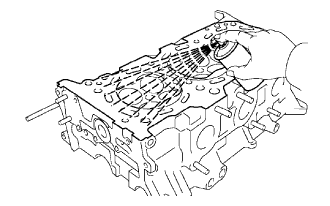
| 17. INSPECT CYLINDER HEAD ASSEMBLY |
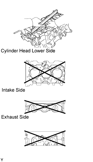 |
Using a precision straight edge and feeler gauge, measure the warpage of the contact surface of the cylinder block and manifolds.
- Standard warpage:
Item Warpage Cylinder head lower 0.05 mm (0.0020 in.) Intake 0.08 mm (0.0031 in.) Exhaust 0.08 mm (0.0031 in.)
- Maximum warpage:
- 0.10 mm (0.0039 in.)
Using a dye, check the intake ports, exhaust ports and cylinder surface for cracks.
If cracked, replace the cylinder head assembly.
 |
| 18. INSPECT INTAKE VALVE |
 |
Using a micrometer, measure the diameter of the valve stem.
- Valve stem diameter:
- 5.470 to 5.485 mm (0.2154 to 0.2159 in.)
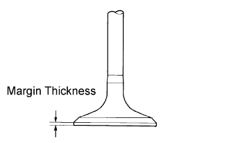
Using vernier calipers, measure the valve head margin thickness.
- Standard margin thickness:
- 1.0 mm (0.03934 in.)
- Minimum margin thickness:
- 0.5 mm (0.0197 in.)
 |
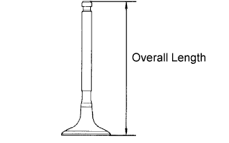
Using vernier calipers, measure the valve's overall length.
- Standard overall length:
- 105.65 mm (4.1594 in.)
- Minimum overall length:
- 105.15 mm (4.1398 in.)
 |
| 19. INSPECT EXHAUST VALVE |
|
Using a micrometer, measure the diameter of the valve stem.
- Valve stem diameter:
- 5.465 to 5.480 mm (0.2151 to 0.2157 in.)
Using vernier calipers, measure the valve head margin thickness.
- Standard margin thickness:
- 1.1 mm (0.0433 in.)
- Minimum margin thickness:
- 0.5 mm (0.0197 in.)
|
Using vernier calipers, measure the valve's overall length.
- Standard overall length:
- 111.50 mm (4.3898 in.)
- Minimum overall length:
- 111.00 mm (4.3701 in.)
|
| 20. INSPECT INTAKE VALVE SEAT |
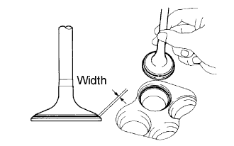 |
Apply a light coat of Prussian blue (or white lead) to the valve face.
Lightly press the valve face against the valve seat.
Check the valve face and valve seat by using the following procedure.
If Prussian blue appears around the entire valve face, the valve face is concentric. If not, replace the valve.
If Prussian blue appears around the entire valve seat, the guide and valve face are concentric. If not, resurface the valve seat.
Check that the valve seat contacts in the middle of the valve face with the width between 1.0 and 1.4 mm (0.039 and 0.055 in.).
| 21. INSPECT EXHAUST VALVE SEAT |
|
Apply a light coat of Prussian blue (or white lead) to the valve face.
Lightly press the valve face against the valve seat.
Check the valve face and valve seat by using to the following procedure.
If Prussian blue appears around the entire valve face, the valve face is concentric. If not, replace the valve.
If Prussian blue appears around the entire valve seat, the guide and valve face are concentric. If not, resurface the valve seat.
Check that the valve seat contacts in the middle of the valve face with the width between 1.2 and 1.6 mm (0.047 and 0.063 in.).
| 22. REPAIR INTAKE VALVE SEAT |
 |
- NOTICE:
- Keep the lip free from foreign matter.
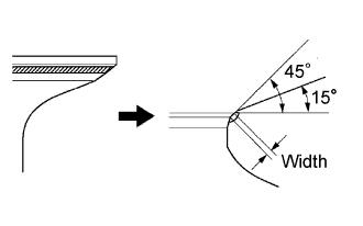
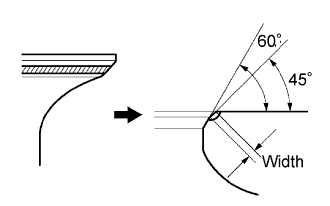
If the seating is too high on the valve face, use 15° and 45° cutters to correct the seat.
If the seating is too low on the valve face, use 45° and 60° cutters to correct the seat.
 |
Handrub the valve and valve seat with an abrasive compound.
Check the valve seating position.
| 23. REPAIR EXHAUST VALVE SEAT |
 |
- NOTICE:
- Keep the lip free from foreign matter.
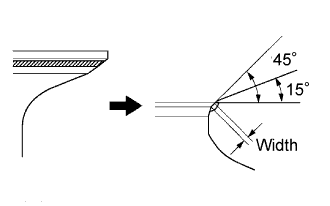
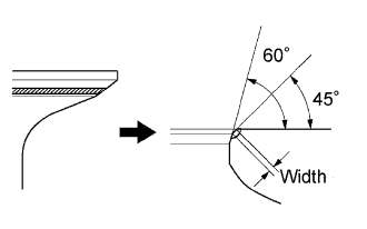
If the seating is too high on the valve face, use 15° and 45° cutters to correct the seat.
If the seating is too low on the valve face, use 45° and 60° cutters to correct the seat.
 |
Handrub the valve and valve seat with an abrasive compound.
Check the valve seating position.
| 24. INSPECT INNER COMPRESSION SPRING |
 |
Using vernier calipers, measure the free length of the inner compression spring.
- Free length:
- 46.51 mm (1.8311 in.)
Using a steel square, measure the deviation of the inner compression spring.
- Maximum deviation:
- 1.0 mm (0.039 in.)
- Maximum angle (reference):
- 2°
 |
| 25. INSPECT VALVE GUIDE BUSH OIL CLEARANCE |
 |
Using a caliper gauge, measure the inside diameter of the guide bush.
- Bush inside diameter:
- 5.510 to 5.530 mm (0.2169 to 0.2177 in.)
Subtract the valve stem diameter measurement from the guide bush inside diameter measurement.
- Standard clearance:
Item Clearance Intake 0.025 to 0.060 m (0.0010 to 0.0024 in.) Exhaust 0.030 to 0.065 mm (0.0012 to 0.0026 in.)
- Maximum oil clearance:
Item Clearance Intake 0.08 mm (0.0032 in.) Exhaust 0.10 mm (0.0039 in.)
If the clearance is greater than the maximum, replace the intake valve and intake guide bush.
For exhaust side:
If the clearance is greater than the maximum, replace the exhaust valve and exhaust guide bush.
| 26. INSPECT CAMSHAFT THRUST CLEARANCE |
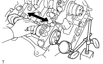 |
Inspect the RH bank camshafts.
Install the RH bank camshafts.
Using a dial indicator, measure the thrust clearance while moving the camshaft back and forth.
- Standard thrust clearance:
- 0.08 to 0.13 mm (0.0031 to 0.0051 in.)
- Maximum thrust clearance:
- 0.15 mm (0.006 in.)
Inspect the LH bank camshafts.
Install the LH bank camshafts.
Using a dial indicator, measure the thrust clearance while moving the camshaft back and forth.
- Standard thrust clearance:
- 0.08 to 0.13 mm (0.0031 to 0.0051 in.)
- Maximum thrust clearance:
- 0.15 mm (0.006 in.)
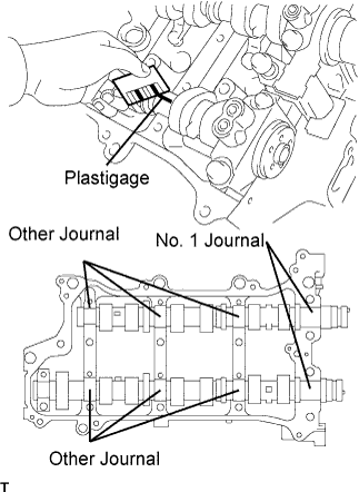
| 27. INSPECT CAMSHAFT OIL CLEARANCE |
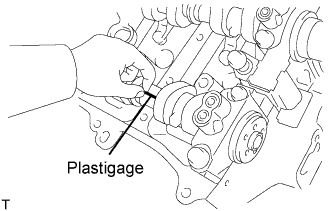 |
Clean the bearing caps, camshaft housing and camshaft journals.
Place the camshafts on the camshaft housing.
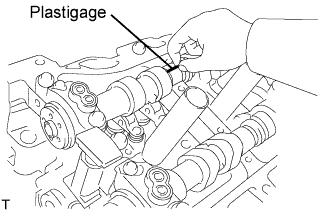
Lay a strip of Plastigage across each of the camshaft journals.
Install the bearing caps.
- NOTICE:
- Do not turn the camshaft.
Remove the bearing caps.
Measure the Plastigage at its widest point.
- Standard oil clearance:
Item Clearance No. 1 journal 0.40 to 0.79 mm (0.0016 to 0.0031 in.) Other journal 0.025 to 0.062 mm (0.00098 to 0.0024 in.)
- Maximum oil clearance:
Item Clearance No. 1 journal 0.10 mm (0.0039 in.) Other journal 0.09 mm (0.0035 in.)
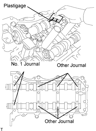
 |
Clean the bearing caps, camshaft housing and camshaft journals.
Place the camshafts on the camshaft housing.
Lay a strip of Plastigage across each of the camshaft journals.
 |
Install the bearing caps.
- NOTICE:
- Do not turn the camshaft.
Remove the bearing caps.
Measure the Plastigage at its widest point.
- Standard oil clearance:
Item Clearance No. 1 journal 0.040 to 0.079 mm (0.0016 to 0.0031 in.) Other journal 0.025 to 0.062 mm (0.00098 to 00024 in.)
- Maximum oil clearance:
Item Clearance No. 1 journal 0.10 mm (0.0039 in.) Other journal 0.09 mm (0.0035 in.)
 |
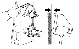
| 28. INSPECT CONNECTING ROD THRUST CLEARANCE |
 |
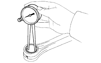
Using a dial indicator, measure the thrust clearance while moving the connecting rod back and forth.
- Standard thrust clearance:
- 0.15 to 0.40 m (0.0059 to 0.0157 in.)
- Maximum thrust clearance:
- 0.50 mm (0.020 in.)
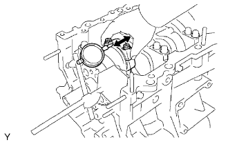
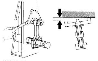
| 29. INSPECT CONNECTING ROD OIL CLEARANCE |
Check that the matchmarks on the connecting rod and cap are aligned to ensure the correct reassembly.
- HINT:
- The matchmarks on the connecting rods and caps are for ensuring the correct reassembly.
Remove the 2 connecting rod cap bolts.
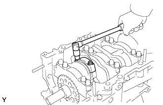 |
Using the 2 removed connecting rod caps bolts, remove the connecting rod cap and lower bearing by wiggling the connecting rod cap right and left.
- HINT:
- Keep the lower bearing inserted to the connecting rod cap.
Clean the crank pin and bearing.
Check the crank pin and bearing for pitting and scratches.
Lay a strip of Plastigage on the crank pin.
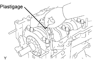 |
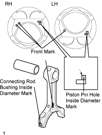
Check that the front mark of the connecting rod cap is facing forward.
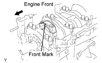 |
Install the connecting rod cap.
- NOTICE:
- Do not turn the crankshaft.
|
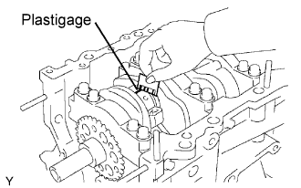
Remove the 2 bolts and connecting rod cap.
Measure the Plastigage at its widest point.
- Standard oil clearance:
- 0.045 to 0.067 mm (0.0018 to 0.0026 in.)
- Maximum oil clearance:
- 0.070 mm (0.0028 in.)
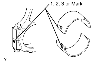
- HINT:
- If replacing a bearing, replace it with one that has the same number as its respective connecting rod cap. Each bearing's standard thickness is indicated by a 1, 2, 3 and 4 mark on its surface.
- Connecting rod diameter:
Mark Diameter 1 56.000 to 56.006 mm (2.2047 to 2.2050 in.) 2 56.007 to 56.012 mm (2.2050 to 2.2052 in.) 3 56.013 to 56.018 mm (2.2052 to 2.2054 in.) 4 56.019 to 56.024 mm (2.2055 to 2.2057 in.)
- Standard bearing center wall thickness:
Mark Thickness 1 1.491 to 1.484 mm (0.0583 to 0.0584 in.) 2 1.484 to 1.487 mm (0.0584 to 0.0585 in.) 3 1.487 to 1.490 mm (0.0585 to 0.0587 in.) 4 1.490 to 1.49 mm (0.0587 to 0.0588 in.)
- Crankshaft pin diameter:
- 52.992 to 53.000 mm (2.0863 to 2.0866 in.)
  |
Completely remove the Plastigage.
| 30. INSPECT CRANKSHAFT THRUST CLEARANCE |
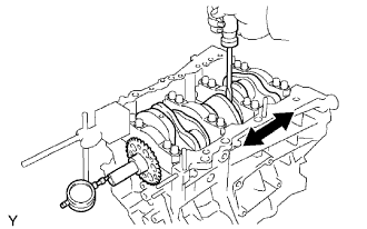 |
Using a dial indicator, measure the thrust clearance while prying the crankshaft back and forth with a screwdriver.
- Standard thrust clearance:
- 0.04 to 0.24 mm (0.0016 to 0.0094 in.)
- Maximum thrust clearance:
- 0.30 mm (00118 in.)
- Thrust washer thickness:
- 2.43 to 2.48 mm (0.0957 to 0.0976 in.)
| 31. INSPECT CYLINDER BLOCK FOR WARPAGE |
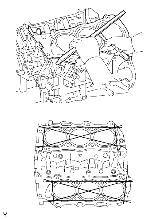 |
Using a precision straight edge and feeler gauge, measure the warpage of the contact surface of the cylinder head gasket.
- Maximum warpage:
- 0.07 mm (0.0028 in.)
Visually check the cylinder for vertical scratches.
If deep scratches are present, rebore all the 4 cylinders. If necessary, replace the cylinder block.
| 32. INSPECT CYLINDER BORE |
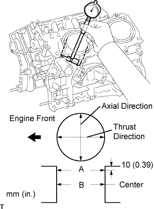 |
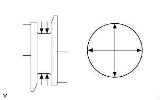
Using a cylinder gauge, measure the cylinder bore diameter at positions A and B in the thrust and axial directions.
- Standard diameter:
- 87.500 to 87.512 mm (3.4449 to 3.445 in.)
- Maximum diameter:
- 87.700 mm (3.4527 in.)
| 33. INSPECT PISTON SUB-ASSEMBLY WITH PIN |
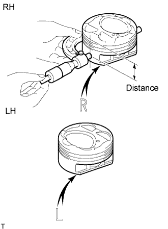 |
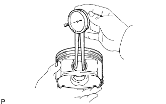
Using a micrometer, measure the piston diameter at right angles to the piston center line where the distance from the piston end is as specified.
- Distance:
- 11.1 mm (0.437 in.)
- Standard diameter:
- 87.476 to 87.486 mm (3.4439 to 3.4443 in.)
- Maximum diameter:
- 87.346 mm (3.4388 in.)
| 34. INSPECT PISTON OIL CLEARANCE |
Measure the cylinder bore diameter in the thrust directions.
Subtract the piston diameter measurement from the cylinder bore diameter measurement.
- Standard oil clearance:
- 0.014 to 0.036 mm (0.0006 to 0.0014 in.)
- Maximum oil clearance:
- 0.06 mm (0.0024 in.)
| 35. INSPECT RING GROOVE CLEARANCE |
 |
Using a feeler gauge, measure the clearance between a new piston ring and the wall of the ring groove.
- Ring groove clearance:
Item Clearance No. 1 0.020 to 0.070 mm (0.0008 to 0.0028 in.) No. 2 0.020 to 0.060 mm (0.0008 to 00024 in.) Oil 0.020 to 0.065 mm (0.0008 to 0.0026 in.)
| 36. INSPECT PISTON RING END GAP |
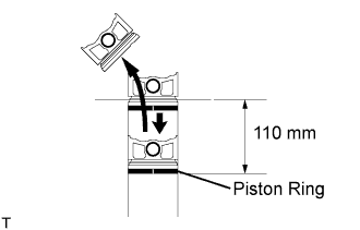 |
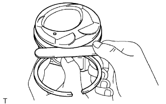
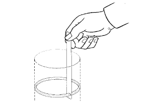
Insert the piston ring into the cylinder bore.
Using a piston, push the piston ring a little beyond the bottom of the ring travel, 110 mm (4.33 in,) from the top of the cylinder block.
Using a feeler gauge, measure the end gap.
- Standard end gap:
Item End gap No. 1 0.23 to 0.33 mm (0.0091 to 0.0130 in.) No. 2 0.50 to 0.60 mm (0.0197 to 0.0236 in.) Oil 0.10 to 0.40 mm (0.0039 to 0.0157 in.)
- Maximum end gap:
Item End gap No. 1 0.50 mm (0.0197 in.) No. 2 0.85 mm (0.0335 in.) Oil 0.70 mm (0.0276 in.)
 |
| 37. INSPECT PISTON PIN OIL CLEARANCE |
 |
Using a caliper gauge, measure the inside diameter of the piston pin hole.
- Piston pin hole inside diameter:
Mark Diameter A 21.998 to 22.001 mm (0.8661 to 0.8662 in.) B 22.001 to 22.004 mm (0.8662 to 0.8663 in.) C 22.004 to 22.007 mm (0.8663 to 0.8664 in.)
Using a micrometer, measure the piston pin diameter.
- Piston pin diameter:
Mark Diameter A 21.997 to 22.000 mm (0.8660 to 0.8661 in.) B 22.000 to 22.003 mm (0.8661 to 0.8663 in.) C 22.003 to 22.006 mm (0.8663 to 0.8664 in.)
 |
Subtract the piston pin diameter measurement from the piston pin hole diameter measurement.
- Standard oil clearance:
- -0.002 to 0.004 mm (-0.00004 to 0.00002 in.)
- Maximum oil clearance:
- 0.015 mm (0.0006 in.)
 |
Using a caliper gauge, measure the inside diameter of the connecting rod bushing.
- Bushing inside diameter:
Mark Diameter A 22.005 to 22.008 mm (0.8663 to 0.8665 in.) B 22.009 to 22.011 mm (0.8665 to 0.8666 in.) C 22.011 to 22.014 mm (0.8666 to 0.8667 in.)
Subtract the piston pin diameter measurement from the bushing inside diameter measurement.
- Standard oil clearance:
- 0.005 to 0.011 mm (0.0002 to 0.0004 in.)
- Maximum oil clearance:
- 0.03 mm (0.0012 in.)
 |
| 38. INSPECT CONNECTING ROD |
 |
Using a rod aligner and feeler gauge, check the connecting rod alignment.
Check for out-of-alignment.
- Maximum out-of-alignment:
- 0.05 mm (0.0020 in.) per 100 mm (0.94 in.)
Check for twist.
- Maximum twist:
- 0.15 mm (0.0059 in.) per 100 mm (3.94 in.)
| 39. INSPECT CONNECTING ROD BOLT |
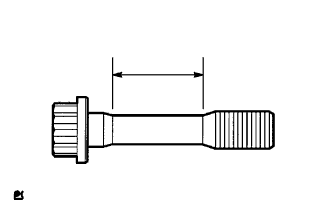 |
Using vernier calipers, measure the tension portion diameter of the bolt.
- Standard diameter:
- 7.2 to 7.3 mm (0.283 to 0.287 in.)
- Minimum diameter:
- 7.0 mm (0.276 in.)
| 40. INSPECT CRANKSHAFT |
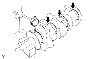 |
Inspect for circle runout.
Place the crankshaft on the V-blocks.
Using a dial indicator, measure the circle runout at the center journal.
- Maximum circle runout:
- 0.06 mm (0.0024 in.)
Inspect the main journals.
Using a micrometer, measure the diameter of each main journal.
- Standard journal diameter:
- 60.988 to 61.00 mm (2.4011 to 2.4016 in.)
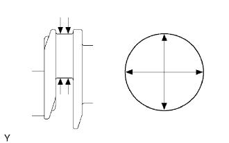
Check each main journal for taper and out-of-round as shown in the illustration.
- Maximum taper and out-of-round:
- 0.02 mm (0.0008 in.)
 |
Inspect the crank pin.
Using a micrometer, measure the diameter of each crank pin.
- Diameter:
- 52.992 to 53.000 mm (2.0863 to 2.0866 in.)
Check each crank pin for taper and out-of-round as shown in the illustration.
- Maximum taper and out-of-round:
- 0.02 mm (0.0008 in.)
 |
| 41. INSPECT CRANKSHAFT OIL CLEARANCE |
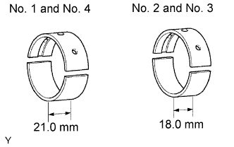 |
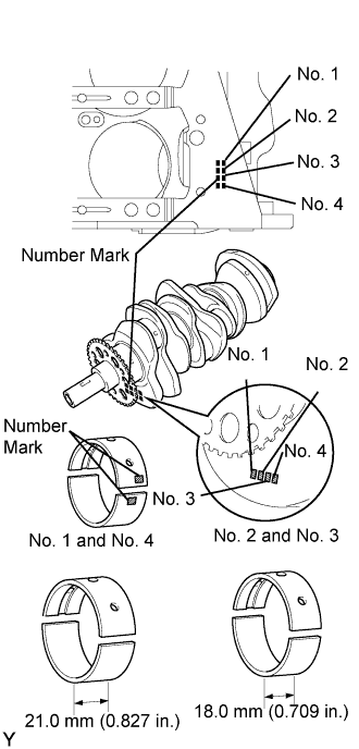
- NOTICE:
- Main bearings come in widths of 18.0 mm (0.709 in.) and 21.0 mm (0.827 in.). Install the 21.0 mm (0.827 in.) bearings in the No. 1 and No. 4 cylinder block journal positions with the main bearing cap. Install the 18.0 mm (0.709 in.) bearings in the No. 2 and No. 3 positions.
Clean the main journal, and both surfaces of the bearing.
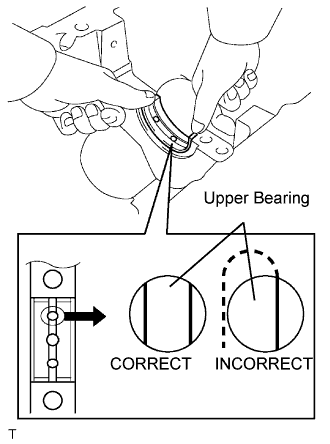
Install the upper bearing.
Install the upper bearing to the cylinder block as shown in the illustration.
- NOTICE:
- Do not apply engine oil to the bearing and its contact surface.
 |
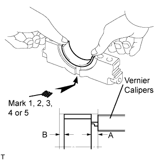
Install the lower bearing.
Install the lower bearing to the bearing cap.
Using vernier calipers, measure the distance between the bearing cap's edge and the lower bearing's edge.
- Dimension (A - B):
- 0.7 mm (0.0276 in.) or less
- NOTICE:
- Do not apply engine oil to the bearing's contact area and backside.
 |
Place the crankshaft on the cylinder block.
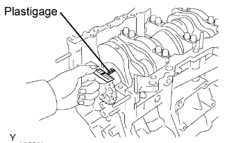
Lay a strip of Plastigage across each journal.
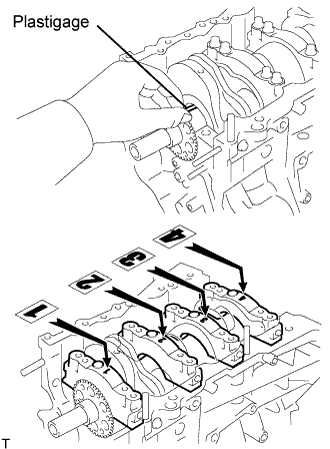 |
Examine the front marks and numbers and install the bearing caps on the cylinder block.
- HINT:
- A number is marked on each main bearing cap to indicate the installation position.
Apply a light coat of engine oil on the threads and under the heads of the bearing cap bolts.
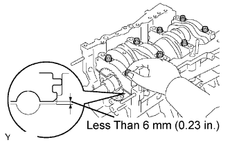
Temporarily install the 8 main bearing cap bolts to the inside positions.
Insert the main bearing cap with your hand until the clearance between the main bearing cap and the cylinder block is less than 6 mm (0.23 in.) by marking the 2 internal bearing cap bolts as a guide.
- Bolt length:
- 100 to 102 mm (3.94 to 4.02 in.)
 |
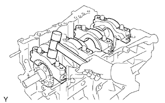
Using a plastic-faced hammer, lightly tap the bearing cap to ensure a proper fit.
 |
Apply a light coat of engine oil on the threads and under the heads of the 8 main bearing cap bolts.
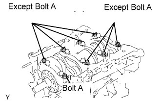
Install the 8 main bearing cap bolts to the outside positions.
- Bolt length:
Item Length Bolt A 100 to 102 mm (3.94 to 4.02 in.) Except bolt A 105.5 to 107.5 mm (4.15 to 4.23 in.)
 |
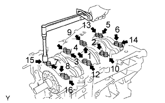
Install and uniformly tighten the 16 main bearing cap bolts in several steps and in the sequence shown in the illustration.
- Torque:
- 61 N*m{622 kgf*cm, 45 ft.*lbf}
 |
Mark the front side of the bearing cap bolts with paint.
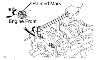 |
Retighten the bearing cap bolts by 90° in the sequence shown.
Check that the painted mark is now at a 90° angle to the front.
- NOTICE:
- Do not turn the crankshaft.
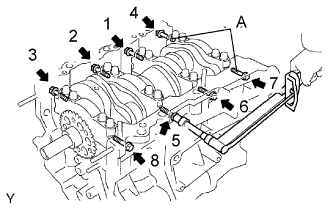
Install and uniformly tighten the 8 main bearing cap bolts in several steps and in the sequence shown in the illustration.
- Torque:
- 26 N*m{265 kgf*cm, 19 ft.*lbf}
- Bolt (A) length:
- 45 mm (1.77 in.)
 |
Remove the main bearing caps.
Measure the Plastigage at its widest point.
- Standard oil clearance:
- 0.026 to 0.047 mm (0.0010 to 0.0019 in.)
- Maximum clearance:
- 0.050 mm (0.0020 in.)
- NOTICE:
- Completely remove the Plastigage after the measurement.
 |
If replacing a bearing, replace it with one having the same number. If the number of the bearing cannot be determined, select the correct bearing by adding together the numbers imprinted on the cylinder block and crankshaft, then refer to the table below for the appropriate bearing number. There are 5 size of standard bearings, marked "1", "2", "3", "4" and "5" accordingly.
Journal bearings: Cylinder block + Crankshaft 0 - 5 6 - 11 12 - 17 18 - 23 24 - 28 Use Bearing "1" "2" "3" "4" "5" - HINT:
- EXAMPLE: Cylinder block "11" + Crankshaft "06" = Total number 17 (Use bearing "3")
- Crankshaft main journal diameter:
Mark Diameter "00" 60.999 to 61.000 mm (2.4015 to 2.4016 in.) "01" 60.998 to 60.999 mm (2.4015 to 2.4015 in.) "02" 60.997 to 60.998 mm (2.4015 to 2.4015 in.) "03" 60.996 to 60.997 mm (2.4014 to 2.4015 in.) "04" 60.995 to 60.996 mm (2.4014 to 2.4014 in.) "05" 60.994 to 60.995 mm (2.4013 to 2.4014 in.) "06" 60.993 to 60.994 mm (2.4013 to 2.4013 in.) "07" 60.992 to 60.993 mm (2.4013 to 2.4013 in.) "08" 60.991 to 60.992 mm (2.4012 to 2.4013 in.) "09" 60.990 to 60.991 mm (2.4012 to 2.4012 in.) "10" 60.989 to 60.990 mm (2.4011 to 2.4012 in.) "11" 60.988 to 60.989 mm (2.4.11 to 2.4011 in.)
- Standard upper bearing center wall thickness (No. 1 and No. 4 journal):
Mark Diameter "1" 2.497 to 2.500 mm (0.0983 to 0.0984 in.) "2" 2.500 to 2.503 mm (0.0984 to 0.0985 in.) "3" 2.503 to 2.506 mm (0.0985 to 0.0987 in.) "4" 2.506 to 2.509 mm (0.0987 to 0.0988 in.) "5" 2.509 to 2.512 mm (0.0988 to 0.0989 in.)
- Standard lower bearing center wall thickness (No. 1 and No. 4 journal):
Mark Diameter "1" 2.481 to 2.484 mm (0.0977 to 0.0978 in.) "2" 2.484 to 2.487 mm (0.0978 to 0.0979 in.) "3" 2.487 to 2.490 mm (0.0979 to 0.0980 in.) "4" 2.490 to 2.493 mm (0.0980 to 0.0981 in.) "5" 2.493 to 2.496 mm (0.0981 to 0.983 in.)
- Standard upper bearing center wall thickness (No. 2 and No. 3 journal):
Mark Diameter "1" 2.481 to 2.484 mm (0.0977 to 0.0978 in.) "2" 2.484 to 2.487 mm (0.0978 to 0.0979 in.) "3" 2.487 to 2.490 mm (0.0979 to 0.0980 in.) "4" 2.490 to 2.493 mm (0.0980 to 0.0981 in.) "5" 2.493 to 2.496 mm (0.0981 to 0.0983 in.)
- Standard lower bearing center wall thickness (No. 2 and No. 3 journal):
Mark Diameter "1" 2.497 to 2.500 mm (0.0983 to 0.0984 in.) "2" 2.500 to 2.503 mm (0.0984 to 0.0985 in.) "3" 2.503 to 2.506 mm (0.0985 to 0.0987 in.) "4" 2.506 to 2.509 mm (0.0987 to 0.0988 in.) "5" 2.509 to 2.512 mm (0.0988 to 0.0989 in.)
 |
| 42. INSPECT CRANKSHAFT BEARING CAP SET BOLT |
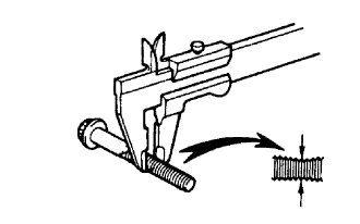 |
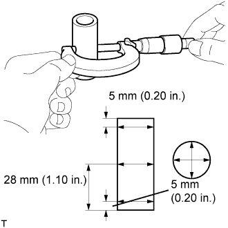
Using vernier calipers, measure the minimum diameter of the compressed thread at the measuring point.
- Standard diameter:
- 10.8 to 11.0 mm (0.4252 to 0.4331 in.)
- Minimum diameter:
- 10.7 mm (0.4213 in.)