Engine Assembly -- Removal |
| 1. DISCHARGE FUEL SYSTEM PRESSURE |
- CAUTION:
- Do not disconnect any part of the fuel system until you have discharged the fuel system pressure.
- Even after discharging the fuel pressure, place a cloth or equivalent over fittings as you separate them to reduce the risk of fuel spray on yourself or in the engine compartment.
Disconnect the cable from the negative (-) battery terminal.
- CAUTION:
- Wait at least 90 seconds after disconnecting the cable from the negative (-) battery terminal to prevent airbag and seat belt pretensioner activation.
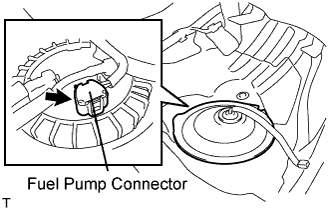
Disconnect the fuel pump connector.
 |
Connect the cable to the negative (-) battery terminal.
Start the engine. After the engine has stopped on its own, turn the engine switch off.
- NOTICE:
- DTC P0171/P0172 (system too lean) may be set.
Crank the engine again, then check that the engine does not start.
Loosen the fuel tank cap, then discharge the pressure in the fuel tank completely.
Connect the fuel pump connector.
| 2. DISCONNECT CABLE FROM NEGATIVE BATTERY TERMINAL |
- CAUTION:
- Wait at least 90 seconds after disconnecting the cable from the negative (-) battery terminal to prevent airbag and seat belt pretensioner activation.
| 3. REMOVE FRONT WHEEL |
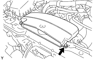
| 4. DRAIN ENGINE OIL |
Remove the drain plug.
| 5. DRAIN ENGINE COOLANT |
- CAUTION:
- Do not remove the radiator cap while the engine and radiator are still hot. Pressurized, hot engine coolant and steam may be released and cause serious burns.
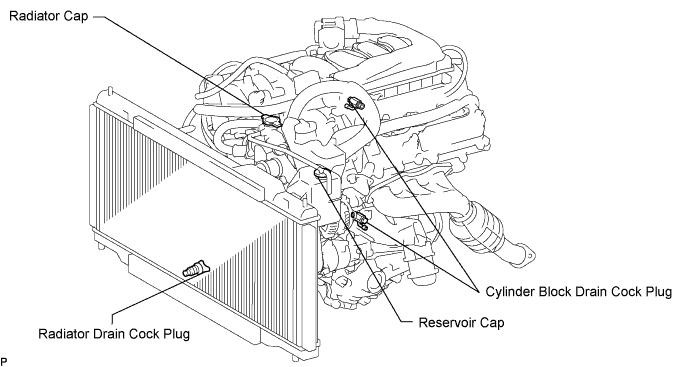
Remove the radiator cap and reservoir cap.
Loosen the radiator drain cock plug and 2 cylinder block drain cock plugs. Then drain the coolant.
- HINT:
- Collect the coolant in a container and dispose of it according to the regulations in your area.
| 6. DRAIN AUTOMATIC TRANSMISSION FLUID |
Add the automatic transmission fluid following the flow chart below.
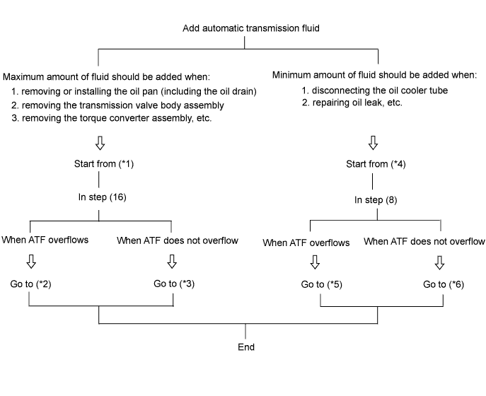
When adding the maximum amount of fluid: [*1]
Lift up the vehicle.
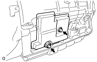
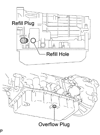
Remove the 2 bolts and transmission case cover.
Remove the refill plug and overflow plug.
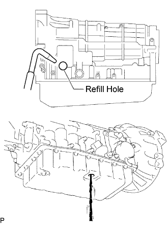
Add ATF through the refill hole until it drains out from the overflow hole.
- NOTICE:
- Be sure to use ATF WS.
Install a new gasket and the overflow plug.
- Torque:
- 20 N*m{204 kgf*cm, 15 ft.*lbf}
Add proper amount of ATF through the refill hole.
- NOTICE:
- Refill amount differs depending on the related procedures indicated below.
Related procedures Refill amount Removal and installation of oil pan
(Including the oil drain)1.3 liters (1.4 US qts, 1.1 lmp.qts) Removal of transmission valve body assembly 3.3 liters (3.5 US qts, 2.9 lmp.qts) Removal of torque converter assembly 4.4 liters (4.7 US qts, 3.9 lmp.qts) Install a new O-ring and the refill plug.
- Torque:
- 39 N*m{400 kgf*cm, 29 ft.*lbf}
Lower the vehicle.
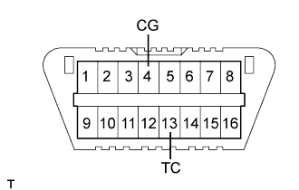
Using SST, create a short-circuit between terminals TC and CG of the DLC3.
- SST
- 09843-18040
Start the engine.
- NOTICE:
- Be sure to place the key inside the cabin in order to start the engine.
- Turn the A/C off.
Slowly move the shift lever from the P to the S position, shift the gear from 1st to 6th and then return the shift lever to the P position.
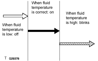
Switch to the fluid temperature detection mode.
- Move the shift lever from the N to the D position, or from D to N, within 1.5 seconds.
- Continue this procedure for 6 seconds or more.
- Standard:
- Meter indicator light "D" comes on for 2 seconds and then goes off.
- Move the shift lever from the N to the D position, or from D to N, within 1.5 seconds.
Return the shift lever to the P position and disconnect terminal TC after confirming the above condition.
Idle the engine to raise fluid temperature.
Lift up the vehicle immediately after meter indicator light "D" comes on.
- NOTICE:
- Add fluid only when the meter indicator light is on.
- Perform this procedure while the engine is idling.
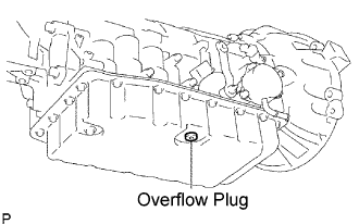
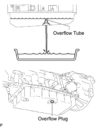
Remove the overflow plug. If ATF overflows, proceed to [*2].
If ATF does not overflow, proceed to [*3].- HINT:
- "Overflow" indicates the condition under which ATF drains out from the overflow tube.
When fluid overflows: [*2]
- NOTICE:
- Capacity of the overflow tube is approximately 3 cc.
Install a new gasket and the overflow plug when the draining ATF has become a trickle.
- Torque:
- 20 N*m{204 kgf*cm, 15 ft.*lbf}
- NOTICE:
- Be careful when handling the drained ATF as it will be hot.
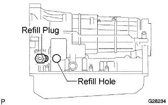
Install a new O-ring and tighten the refill plug.
- Torque:
- 39 N*m{400 kgf*cm, 29 ft.*lbf}
Install the transmission case cover with the 2 bolts.
- Torque:
- 5.4 N*m{55 kgf*cm, 48 in.*lbf}
Lower the vehicle.
Turn the engine switch off and remove the SST.
 |
When fluid does not overflow:[*3]
Remove the refill plug.
Add ATF through the refill hole until it drains out from the overflow hole.
Install a new gasket and the overflow plug when the draining ATF has become a trickle.
- Torque:
- 20 N*m{204 kgf*cm, 15 ft.*lbf}
Install a new O-ring and tighten the refill plug.
- Torque:
- 39 N*m{400 kgf*cm, 29 ft.*lbf}
Install the transmission case cover with the 2 bolts.
- Torque:
- 5.4 N*m{55 kgf*cm, 48 in.*lbf}
Lower the vehicle.
Turn the engine switch off and remove the SST.
When adding a minimum amount of fluid: [*4]
Using SST, create a short-circuit between terminals TC and CG of the DLC3.
- SST
- 09843-18040
Start the engine.
- NOTICE:
- Be sure to place the key inside the cabin in order to start the engine.
- Turn the A/C off.
Slowly move the shift lever from the P to the S position, shift the gear from 1st to 6th and then return the shift lever to the P position.
Switch to the fluid temperature detection mode.
- Move the shift lever from the N to the D position, or from D to N, within 1.5 seconds.
- Continue this procedure for 6 seconds or more.
- Standard:
- Meter indicator light "D" comes on for 2 seconds and then goes off.
- Move the shift lever from the N to the D position, or from D to N, within 1.5 seconds.
Return the shift lever to the P position and disconnect terminal TC after confirming the above condition.
Idle the engine to raise fluid temperature.
Lift up the vehicle immediately after meter indicator light "D" comes on.
- NOTICE:
- Add fluid only when the meter indicator light is on.
- Perform this procedure while the engine is idling.
Remove the overflow plug. If ATF overflows, proceed to [*5]. If ATF does not overflow, proceed to [*6].
- HINT:
- "Overflow" indicates the condition under which ATF drains out from the overflow tube.
When fluid overflows: [*5]
Install a new gasket and the overflow plug when the draining ATF has become a trickle.
- Torque:
- 20 N*m{204 kgf*cm, 15 ft.*lbf}
- NOTICE:
- Be careful when handling the drained ATF as it will be hot.
Install the transmission case cover with the 2 bolts.
- Torque:
- 5.4 N*m{55 kgf*cm, 48 in.*lbf}
Lower the vehicle.
Turn the engine switch off and remove the SST.
When fluid does not overflow: [*6]
Remove the refill plug.
Add ATF through the refill hole until it drains out from the overflow hole.
Install a new gasket and the overflow plug when the draining ATF has become a trickle.
- Torque:
- 20 N*m{204 kgf*cm, 15 ft.*lbf}
Install a new O-ring and tighten the refill plug.
- Torque:
- 39 N*m{400 kgf*cm, 29 ft.*lbf}
Install the transmission case cover with the 2 bolts.
- Torque:
- 5.4 N*m{55 kgf*cm, 48 in.*lbf}
Lower the vehicle.
Turn the engine switch off and remove the SST.
| 7. REMOVE COOL AIR INTAKE DUCT SEAL |
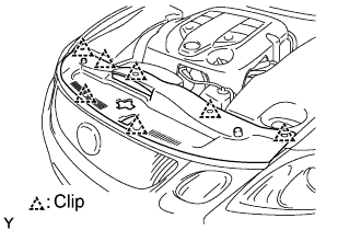 |
Remove the 7 clips and intake duct seal.
| 8. REMOVE ENGINE ROOM COVER SIDE RH |
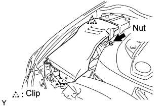 |
Remove the nut, 2 clips and side cover.
| 9. REMOVE ENGINE ROOM SIDE COVER LH |
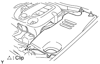 |
Remove the 3 clips and side cover.
| 10. REMOVE V-BANK COVER SUB-ASSEMBLY |
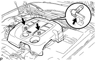 |
Remove the 2 nuts and V-bank cover.
| 11. REMOVE ENGINE UNDER COVER |
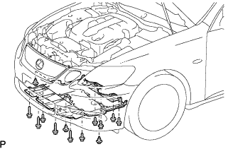 |
Using a clip remover, remove the 3 clips.
Remove the 10 screws and under cover.
| 12. REMOVE NO. 2 ENGINE UNDER COVER |
Remove the 4 screws, 2 grommets, 2 spacers and under cover.
| 13. REMOVE FRONT EXHAUST PIPE ASSEMBLY |
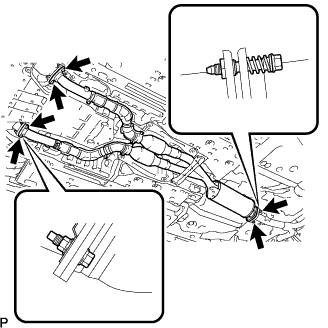 |
Remove the 4 bolts and 4 nuts.
Disconnect the exhaust pipe front ends from the exhaust manifold and remove the 2 gaskets.
Remove the 2 bolts, 2 compression springs, exhaust pipe and gasket.
| 14. REMOVE PROPELLER WITH CENTER BEARING SHAFT ASSEMBLY |
Put matchmarks on both flanges.
 |
Remove the 4 nuts, bolts and washers.
- HINT:
- If the flange connection is hard to separate, temporarily tighten one nut only and evenly tap the flange with a brass bar and hammer to separate the propeller shaft assembly from the differential companion flange.
Remove the 2 bolts, 2 center support bearing washers and center support bearing.
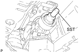
 |
Insert SST in the transmission to prevent oil leakage.
- SST
- 09325-40010
- NOTICE:
- Be careful not to damage the oil seal.
 |
| 15. REMOVE NO. 1 AIR CLEANER INLET |
 |
Remove the bolt and air cleaner inlet.
| 16. REMOVE AIR CLEANER ASSEMBLY WITH HOSE |
Disconnect the ventilation hose from the cylinder head.
 |
Disconnect the MAF meter connector.
 |
Disconnect the clamp from the air cleaner.
Disconnect the VSV (for EVAP).
 |
Loosen the hose clamp.
Remove the 3 bolts and air cleaner case.
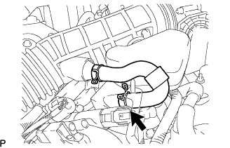
| 17. DISCONNECT RADIATOR HOSE INLET |
Disconnect the hose from the water inlet with thermostat and radiator tank upper.
| 18. DISCONNECT RADIATOR HOSE OUTLET |
Disconnect the hose from the water inlet and radiator tank lower.
| 19. DISCONNECT RADIATOR RESERVE TANK HOSE |
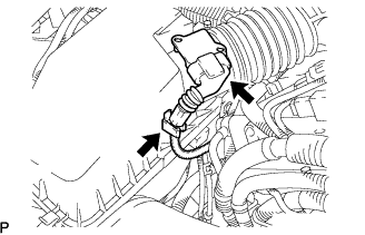
| 20. DISCONNECT UNION TO CHECK VALVE HOSE |
 |
Remove the clamp and disconnect the union to check valve hose.
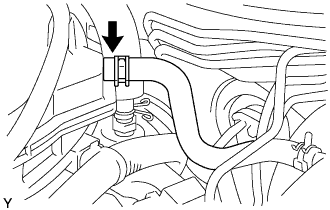
| 21. DISCONNECT HEATER WATER INLET HOSE A |
 |
Disconnect the inlet hose.
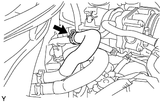
| 22. DISCONNECT HEATER WATER OUTLET HOSE A |
 |
Disconnect the outlet hose.
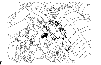
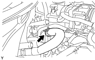
| 23. DISCONNECT FUEL MAIN TUBE |
Remove the fuel pipe clamp.
 |
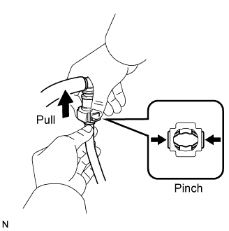
Pinch and pull the fuel hose's connector to disconnect it from the fuel pipe.
- NOTICE:
Check for foreign matter in the fuel hose and around the fuel hose's connector. Clean if necessary. Foreign matter can affect the O-ring's ability to seal the connector and fuel pipe.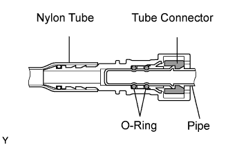
- Do not use any tools to separate the connector and fuel pipe.
- Do not forcefully bend or twist the hose.
- Keep the connector and pipe free from foreign matter.
Put the connector in a plastic bag to prevent damage and contamination.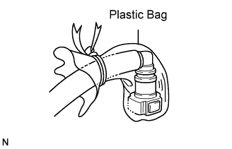
- If the connector and fuel pipe are stuck together, pinch the connector and turn it carefully to disconnect it.
 |
| 24. REMOVE ENGINE ECM COVER |
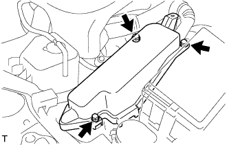 |
Remove the 3 bolts and engine room ECM cover.
| 25. DISCONNECT ENGINE WIRE |
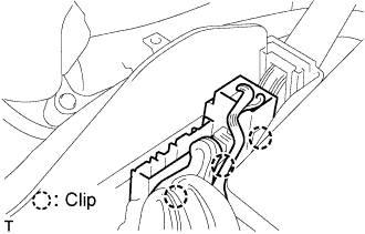 |
Disconnect the ECM connectors.
Using a screwdriver, disconnect the connector holder.
Disconnect the 6 ECM connectors.
Remove the nut and disconnect the battery positive (+) cable.
Remove the engine room No. 1 relay block cover.
Remove the nut and disconnect the wire from the engine room No. 1 junction block.
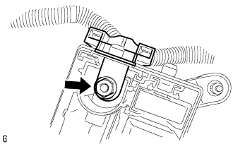 |
Remove the bolt and disconnect the ground cable.
| 26. REMOVE FAN AND GENERATOR V BELT |
While releasing the belt tension by turning the belt tensioner counterclockwise, and remove the V-ribbed belt from the belt tensioner.
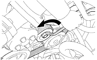 |
While turning the belt tensioner counterclockwise, align with its holes, and then insert the 5 mm bi-hexagon wrench into the holes to fix the V-ribbed belt tensioner.
 |
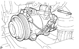
| 27. REMOVE COMPRESSOR WITH PULLEY ASSEMBLY |
 |
Disconnect the magnetic clutch connector.
Remove the 3 bolts and nut.
Using an E8 "torx" socket, remove the stud bolt and with pulley compressor.
- HINT:
- It is not necessary to completely remove the compressor. With the hoses connected to the compressor, hang the compressor on the vehicle body with a rope.
 |
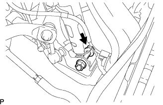
| 28. DISCONNECT HEIGHT CONTROL SENSOR LINK |
Remove the nut and disconnect the height control sensor link.
| 29. REMOVE FRONT SUSPENSION MEMBER PROTECTOR LOWER |
Remove the 4 bolts and protector.
| 30. REMOVE TIE ROD ASSEMBLY RH |
- SST
- 09628-00011
- HINT:
- Perform the same procedure as for the LH side.
| 31. REMOVE TIE ROD ASSEMBLY LH |
Remove the clip and the castle nut.
Using SST, separate the tie rod end LH from the steering knuckle.
- SST
- 09628-00011
- NOTICE:
- Hang SST with a string, etc. to prevent it from falling.
- Do not damage the front disc brake dust cover.
- Do not damage the ball joint dust cover.
- Do not damage the steering knuckle.
 |
| 32. REMOVE FRONT SHOCK ABSORBER ASSEMBLY RH |
Support the front suspension lower arm with a jack. Be sure to place a wooden block between the jack and the front suspension lower arm to avoid damage.
 |
Loosen the bolt while holding the nut. Separate the lower part of the front shock absorber from the front suspension lower arm.
- NOTICE:
- Do not remove the nut.
Loosen the lock nut of the front shock absorber.
- NOTICE:
- Do not remove the lock nut.
- Loosen the lock nut only when disassembling the front shock absorber with coil spring.
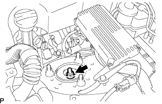 |
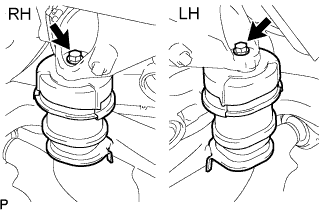
Remove the 3 nuts from the upper side of the front suspension support.
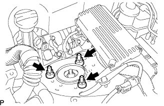 |
Slowly lower the jack. Remove the bolt and nut from the lower side to remove the front shock absorber with coil spring.
| 33. REMOVE FRONT SHOCK ABSORBER ASSEMBLY LH |
Support the front suspension lower arm with a jack. Be sure to place a wooden block between the jack and the front suspension lower arm to avoid damage.
|
Loosen the bolt while holding the nut. Separate the lower part of the front shock absorber from the front suspension lower arm.
- NOTICE:
- Do not remove the nut.
Loosen the lock nut of the front shock absorber.
- NOTICE:
- Do not remove the lock nut.
- Loosen the lock nut only when disassembling the front shock absorber with coil spring.
|
Remove the 3 nuts from the upper side of the front suspension support.
|
Slowly lower the jack. Remove the bolt and nut from the lower side to remove the front shock absorber with coil spring.
| 34. REMOVE NO. 2 STEERING INTERMEDIATE SHAFT ASSEMBLY |
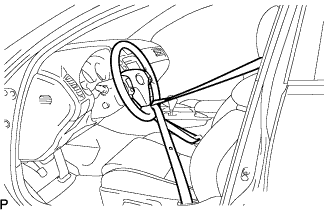
Fix the steering wheel with the seat belt in order to prevent rotation.
- HINT:
- This operation is useful to prevent damage to the spiral cable.
 |
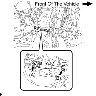
Loosen bolt (A) and remove bolt (B), then slide the steering intermediate shaft assembly No.2.
- HINT:
- Do not remove bolt (A).
- Do not disconnect the steering intermediate shaft assembly No.2 from the power steering link assembly.
 |
Put matchmarks on the steering intermediate shaft assembly No.2 and the power steering link assembly.
Separate the intermediate shaft assembly No.2 from the power steering link assembly.
| 35. REMOVE FRONT LOWER BALL JOINT RH |
| 36. REMOVE FRONT LOWER BALL JOINT LH |
| 37. DISCONNECT POWER STEERING LINK WIRE HARNESS |
Remove bolt (A) to disconnect the earth wire from the bracket.
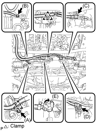 |
Remove the 2 clamps to disconnect the wire harness from the bracket.
Disconnect 2 connectors (C) and (D) from the power steering link assembly.
Release the lock of connector (E) and disconnect connector (E) from the power steering link assembly.
Remove bolt (B) and the power steering earth wire from the power steering link assembly.
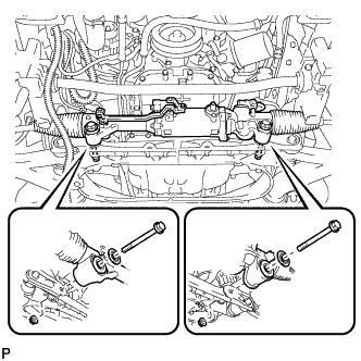
Remove the 2 bolts, 2 washers, 2 nuts, and the power steering link assembly from the front suspension cross member.
 |
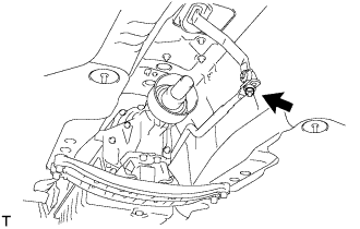
| 38. DISCONNECT FLOOR SHIFT GEAR SHIFTING ROD SUB-ASSEMBLY |
Set the shift lever to the neutral position.
Remove the nut, and separate the floor shift gear shifting rod sub-assembly.
 |
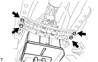
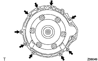
| 39. REMOVE ENGINE AND TRANSMISSION ASSEMBLY |
Set the engine lifter.
Remove the 4 bolts, then separate the engine rear mounting member.
 |
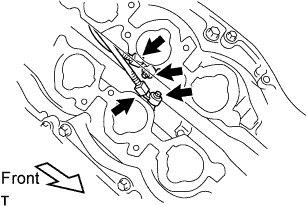
Remove the 12 bolts shown in the illustration.
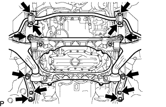 |
Operate the engine lifter, then slowly remove the engine from the vehicle.
- NOTICE:
- Make sure the engine is clear of all wiring and hoses.
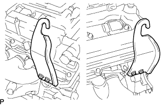
Install the 2 engine hangers with the 4 bolts as shown in the illustration.
Part No.: No. 1 Engine hanger 12281 - 31070 No. 2 Engine hanger 12282 - 31070 Bolts 91671 - 10825 - Torque:
- 33 N*m{336 kgf*cm, 24 ft.*lbf}
 |
Attach an engine sling device and hang the engine with a chain block.
| 40. REMOVE AUTOMATIC TRANSMISSION ASSEMBLY |
Remove the 9 bolts and automatic transmission assembly.
 |
| 41. REMOVE DRIVE PLATE AND RING GEAR SUB-ASSEMBLY |
 |
Using SST, hold the crankshaft.
- SST
- 09213-70011(09213-70020)
09330-00021
Remove the 8 bolts, front spacer, drive plate and rear spacer.
 |
| 42. REMOVE FRONT ENGINE MOUNTING INSULATOR |
 |
Remove the 2 bolts, then remove the front suspension crossmember sub-assembly from the engine.
| 43. FIX ENGINE ON ENGINE STAND |
Fix the engine onto a engine stand with the bolts.
| 44. REMOVE ENGINE WIRE |
Remove the engine wire from the engine.
| 45. REMOVE OIL DIPSTICK SUB-ASSEMBLY |
 |
Remove the oil dipstick.
Remove the 2 bolts, then remove the No. 1 and No. 2 oil dipstick guide.
Remove the O-ring from the oil level gauge guide.
| 46. REMOVE EXHAUST MANIFOLD SUB-ASSEMBLY RH |
Disconnect the heated oxygen sensor connector.
Remove the 6 nuts, exhaust manifold and gasket.
| 47. INSPECT EXHAUST MANIFOLD SUB-ASSEMBLY RH |
 |
Using a precision straightedge and feeler gauge, measure the surface contacting the cylinder head for warpage.
- Maximum warpage:
- 0.7 mm (0.028 in.)
- HINT:
- The maximum allowable warpage of each installation surface is 0.3 mm (0.012 in.).
| 48. REMOVE EXHAUST MANIFOLD SUB-ASSEMBLY LH |
Disconnect the heated oxygen sensor connector.
Remove the 6 nuts, exhaust manifold and gasket.
| 49. INSPECT EXHAUST MANIFOLD SUB-ASSEMBLY LH |
 |
Using a precision straightedge and feeler gauge, measure the surface contacting the cylinder head for warpage.
- Maximum warpage:
- 0.7 mm (0.028 in.)
- HINT:
- The maximum allowable warpage of each installation surface is 0.3 mm (0.012 in.).
| 50. REMOVE GENERATOR ASSEMBLY |
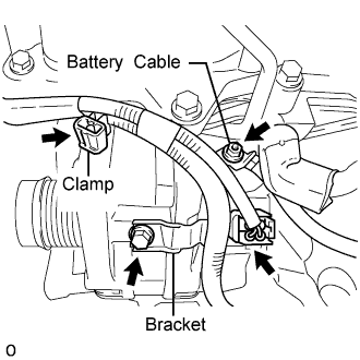 |
Detach the clamp, and remove the bolt from the generator.
Disconnect the generator connector.
Detach the rubber cap, and then remove the nut and battery cable.
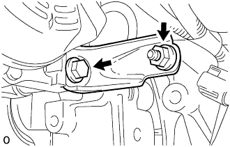
Remove the nut, bolt and generator bracket.
 |
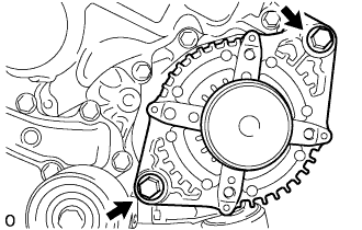
Remove the 2 bolts and generator.
 |
| 51. REMOVE NO. 2 IDLER PULLEY SUB-ASSEMBLY |
Remove the bolt, plate and idler pulley.
| 52. REMOVE V-RIBBED BELT TENSIONER ASSEMBLY |
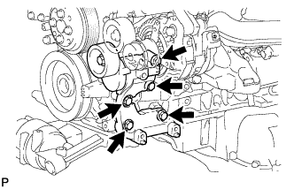 |
Remove the 5 bolts, then remove the V-ribbed belt tensioner assembly.
| 53. REMOVE WATER PUMP PULLEY |
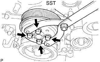 |
Using SST, hold the water pump pulley.
- SST
- 09960-10010(09962-01000,09963-00700)
Remove the 4 bolts and water pump pulley.
| 54. DISCONNECT NO. 1 WATER BY-PASS HOSE |
| 55. DISCONNECT NO. 2 WATER BY-PASS HOSE |
| 56. REMOVE REAR ENGINE COVER SUB-ASSEMBLY |
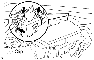 |
Remove the 3 clips and engine cover.
| 57. REMOVE NO. 3 WATER BY-PASS PIPE |
Remove the bolt and water by-pass pipe.
| 58. REMOVE NO. 4 WATER BY-PASS PIPE |
Remove the bolt and water by-pass pipe.
| 59. REMOVE INTAKE AIR SURGE TANK SUB-ASSEMBLY |
Remove the 2 bolts and intake manifold stay.
Remove the 4 bolts and 2 surge tank stays.
Using a 5 mm hexagon socket wrench, remove the 7 bolts, 2 nuts and gasket.
- HINT:
- Cover the intake manifold port to prevent foreign matter from entering it.
 |
| 60. INSPECT INTAKE AIR SURGE TANK SUB-ASSEMBLY |
 |
Using a precision straightedge and feeler gauge, measure the surface contacting the cylinder head for warpage.
- Maximum warpage:
Specified Condition Condition When installed 0.3 mm (0.011 in.) When not installed 2.5 mm (0.098 in.)
| 61. REMOVE FUEL PRESSURE PULSATION DAMPER ASSEMBLY |
Remove the holder.
 |
Pull out the fuel pressure pulsation damper from the fuel delivery pipe.
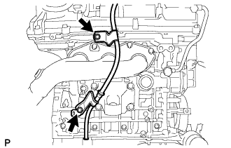
| 62. REMOVE FUEL DELIVERY PIPE SUB-ASSEMBLY |
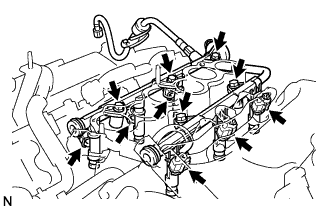 |
Remove the bolt and disconnect the No. 1 fuel hose from the cylinder head cover.
Disconnect the 6 fuel injector connectors.
Remove the 5 bolts and the fuel delivery pipe together with the 6 fuel injectors.
- NOTICE:
- Be careful not to drop the injectors when removing the fuel delivery pipe.
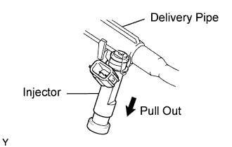
| 63. REMOVE FUEL INJECTOR ASSEMBLY |
Pull out the 6 fuel injectors from the delivery pipe.
 |
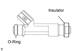
Remove the 6 insulators and 6 O-rings from the 6 fuel injectors.
 |
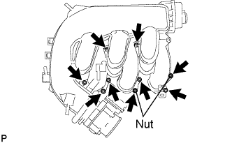
| 64. REMOVE INTAKE MANIFOLD |
 |
Remove the 6 bolts, 4 nuts, intake manifold and gasket.
- HINT:
- Cover the cylinder head intake port to prevent foreign matter from entering it.
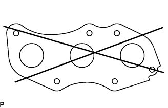
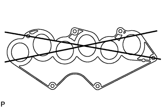
| 65. INSPECT INTAKE MANIFOLD |
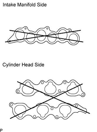 |
Surge tank side:
Using a precision straightedge and feeler gauge, measure the surface contacting the cylinder head for warpage.
- Maximum warpage:
- 0.1 mm (0.003 in.)
Cylinder head side:
Using a precision straightedge and feeler gauge, measure the surface contacting the cylinder head for warpage.
- Maximum warpage:
- 0.1 mm (0.003 in.)
| 66. REMOVE KNOCK SENSOR |
 |
Remove the 2 bolts and 2 sensors.
| 67. REMOVE ENGINE MOUNTING BRACKET RH |
Remove the 4 bolts and mounting bracket.
| 68. REMOVE ENGINE MOUNTING BRACKET LH |
Remove the 4 bolts and mounting bracket.
| 69. REMOVE OIL FILLER CAP SUB-ASSEMBLY |
| 70. REMOVE IGNITION COIL ASSEMBLY |
Remove the 6 bolts and 6 ignition coils.
| 71. REMOVE ENGINE OIL LEVEL SENSOR |
Remove the 4 bolts, then remove the oil level sensor and gasket.
| 72. REMOVE OIL PRESSURE SWITCH ASSEMBLY |
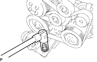 |
Using a 24 mm deep socket wrench, remove the oil pressure switch.
| 73. REMOVE ENGINE COOLANT TEMPERATURE SENSOR |
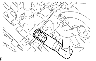 |
Using a 19 mm deep socket wrench, remove the temperature sensor.