Dtc P0504 Brake Switch A / B Correlation
Engine. Lexus Gs430, Gs300. Uzs190 Grs190
DESCRIPTION
WIRING DIAGRAM
INSPECTION PROCEDURE
CHECK STOP LIGHT SWITCH
INSPECT STOP LIGHT SWITCH
READ DATA LIST
CHECK WIRE HARNESS (STOP LIGHT SWITCH - ECM)
DTC P0504 Brake Switch "A" / "B" Correlation |
DTC P0571 Brake Switch "A" Circuit |
DESCRIPTION
In addition to turning on the stop lights, the stop light switch signals are used for a variety of engine, transmission and suspension functions. The stop light switch is designed with 2 complementary signal outputs, STP and ST1-. The ECM analyzes these signal outputs to detect malfunctions in the stop light switch.DTC No.
| DTC Detection Condition
| Trouble Area
|
P0504
| - Conditions (a), (b) and (c) continue for 0.5 sec. or more:
- (a) Engine switch on (IG)
- (b) Brake pedal released
- (c) STP signal is OFF when the ST1- signal is OFF
| - Short in stop light switch signal circuit
- Stop light fuse
- Stop light switch
- ECM
|
- HINT:
- Normal condition is as shown in the table below. The signals can be read using the intelligent tester.
Signal
| Brake Pedal Released
| In Transition
| Brake Pedal Depressed
|
STP
| OFF
| ON
| ON
|
ST1-
| ON
| ON
| OFF
|
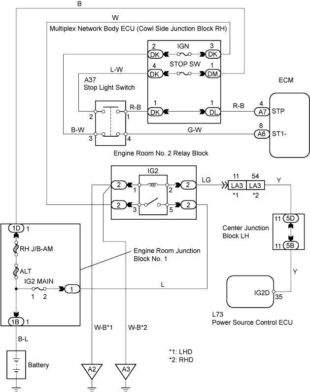
WIRING DIAGRAM
INSPECTION PROCEDURE
| 1.CHECK STOP LIGHT SWITCH |
Check if the stop lights turn on and off normally when the brake pedal is depressed and released.
| | REPAIR OR REPLACE STOP LIGHT SWITCH |
|
|
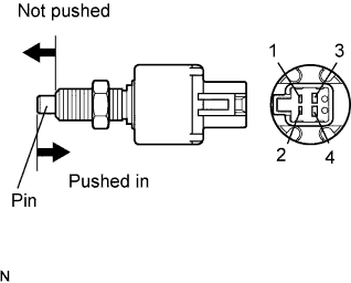
| 2.INSPECT STOP LIGHT SWITCH |
Disconnect the A37 stop light switch.
Measure the resistance of the switch.
- Standard resistance:
Tester Connection
| Switch Condition
| Specified Condition
|
1 - 2
| Switch pin not pushed
| Below 1 Ω
|
3 - 4
| Switch pin not pushed
| 10 kΩ or higher
|
1 - 2
| Switch pin pushed in
| 10 kΩ or higher
|
3 - 4
| Switch pin pushed in
| Below 1 Ω
|
| | REPLACE STOP LIGHT SWITCH |
|
|
Connect the intelligent tester to the DLC3.
Turn the engine switch on (IG).
Enter the following menus: Powertrain / Engine / Data List / Primary / Stop Light Switch.
Confirm the stop light switch status when the brake pedal is depressed and released.
- OK:
Brake Pedal Condition
| Specified Condition
|
Depressed
| STP Signal ON
|
Released
| STP Signal OFF
|
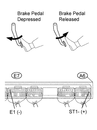
Measure the voltage of the ECM when the brake pedal is depressed and released.
- Standard voltage:
Tester Connection
| Brake Pedal Condition
| Specified Condition
|
A6-8 (ST1-) - E7-7 (E1)
| Depressed
| Below 1.5 V
|
A6-8 (ST1-) - E7-7 (E1)
| Released
| 7.5 to 14 V
|
| | CHECK FOR INTERMITTENT PROBLEMS |
|
|
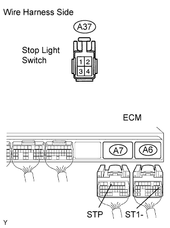
| 4.CHECK WIRE HARNESS (STOP LIGHT SWITCH - ECM) |
Disconnect the A37 stop light switch connector.
Disconnect the A6 and A7 ECM connectors.
Measure the resistance of the wire harness side connectors.
- Standard resistance:
Tester Connection
| Specified Condition
|
A37-1 - A7-4 (STP)
| Below 1 Ω
|
A37-4 - A6-8 (ST1-)
| Below 1 Ω
|
A37-1 or A7-4 (STP) - Body ground
| 10 kΩ or higher
|
A37-4 or A6-8 (ST1-) - Body ground
| 10 kΩ or higher
|
| | REPAIR OR REPLACE HARNESS AND CONNECTOR |
|
|