Engine. Lexus Gs430, Gs300. Uzs190 Grs190
3Uz-Fe Engine Control System. Lexus Gs430, Gs300. Uzs190 Grs190
DTC P0016 Crankshaft Position - Camshaft Position Correlation (Bank 1 Sensor A) |
DTC P0018 Crankshaft Position - Camshaft Position Correlation (Bank 2 Sensor A) |
DESCRIPTION
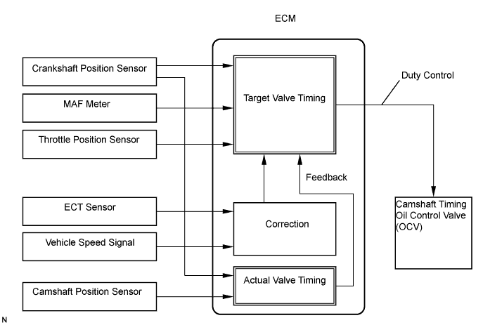
The Variable Valve Timing (VVT) system controls the intake camshaft to provide the optimal valve timing for every driving condition. This control is performed based on signals regarding intake air volume, throttle position and engine coolant temperature.The ECM controls the Oil Control Valve (OCV), based on the signals output from several sensors. The VVT controller regulates the intake camshaft angle using oil pressure through the OCV. As a result, the relative position between the camshaft and the crankshaft becomes optimal, and the engine torque improves, fuel economy improves, and exhaust emissions decrease under overall driving conditions. Also, the ECM detects the actual valve timing using the signals from the camshaft position sensor and the crankshaft position sensor, and performs feedback control. This is how target valve timing is achieved by the ECM.
| DTC No. | DTC Detection Condition | Trouble Area |
| P0016 | Deviation in crankshaft position sensor signal and VVT sensor 1 signal (2 trip detection logic) |
|
| P0018 | Deviation in crankshaft position sensor signal and VVT sensor 2 signal (2 trip detection logic) |
|
MONITOR DESCRIPTION
- The ECM optimizes the valve timing using the VVT system to control the intake valve camshaft. The VVT system includes the ECM, the OCV and the VVT controller. The ECM sends a target duty-cycle control signal to the OCV. This control signal, applied to the OCV, regulates the oil pressure supplied to the VVT controller. The VVT controller can advance or retard the intake valve camshaft. The ECM calibrates the valve timing of the VVT system by setting the camshaft to the maximum retard angle when the engine is idling. The ECM closes the OCV to retard the cam. The ECM stores this value as VVT learned value. When the difference between the target valve timing and the actual valve timing is more than 5° crankshaft angle the ECM learns it.
If the learned value meets both of the following conditions (a) and (b), the ECM interprets this as a defect in the VVT system and sets a DTC. - VVT learning value is less than 20°crankshaft angle or more than 39°crankshaft angle.
- Above condition continues for 18 seconds or more.
- This DTC shows that the camshaft was installed toward the crankshaft at an incorrect angle (for example: jumped tooth of timing belt).
This monitor runs after the engine is idling for 5 minutes.
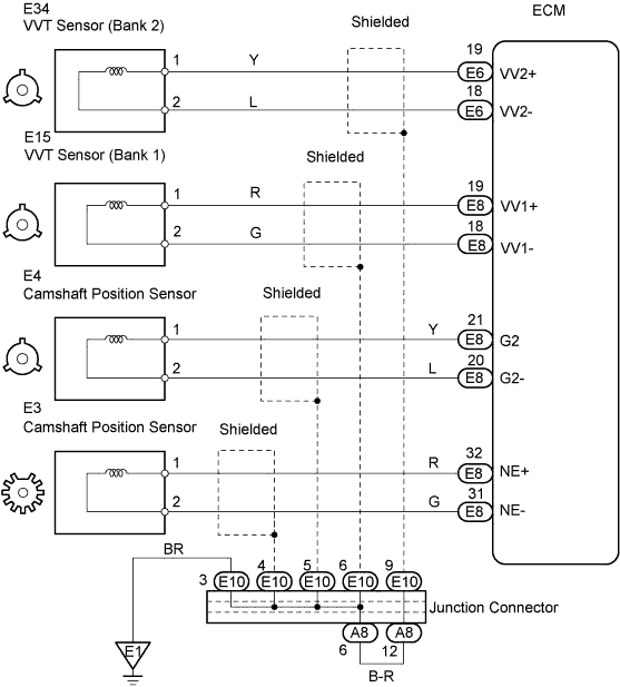
WIRING DIAGRAM
INSPECTION PROCEDURE
- HINT:
- Read freeze frame data using the intelligent tester. Freeze frame data records the engine conditions when a malfunction is detected. When troubleshooting, freeze frame data can help determine if the vehicle was running or stopped, if the engine was warmed up or not, if the air-fuel ratio was LEAN or RICH, and other data from the time the malfunction occurred.
- If DTC P0016 is displayed, check the bank 1 VVT OCV.
- If DTC P0018 is displayed, check the bank 2 VVT OCV.
- Bank 1 includes cylinder No. 1, but bank 2 does not. Cylinder No. 1 is located in the front part of the engine, opposite the transmission.
| 1.CHECK VALVE TIMING |
 |
Remove the engine cover.
Remove the drive belt.
Remove the timing belt cover LH and RH.
Turn the crankshaft to align the matchmarks of the crankshaft.
Align the notch of the crankshaft pulley with the "0" position.
Confirm whether the matchmarks of the camshaft pulley and cylinder head cover are facing each other.
If the matchmarks are not facing each other, turn the crankshaft clockwise by 360°. Confirm again if the matchmarks are facing each other.
- OK:
- The matchmarks of the camshaft pulley and the cylinder head cover face each other when the notch of the crankshaft pulley is in the "0" position.
|
| ||||
| OK | ||
| ||