Engine. Lexus Gs430, Gs300. Uzs190 Grs190
3Uz-Fe Engine Control System. Lexus Gs430, Gs300. Uzs190 Grs190
Sfi System -- Freeze Frame Data |
| DESCRIPTION |
- Freeze frame data records the engine conditions (fuel system, calculated load, engine coolant temperature, fuel trim, engine speed, vehicle speed, etc.) when a malfunction is detected. When troubleshooting, freeze frame data can help determine if the vehicle was running or stopped, if the engine was warmed up or not, if the air-fuel ratio was LEAN or RICH, and other data from the time the malfunction occurred.
- HINT:
- If it is not possible to replicate the problem even though a DTC is detected, confirm the freeze frame data.
The ECM records engine conditions in the form of freeze frame data every 0.5 seconds. Using the intelligent tester, 5 separate sets of freeze frame data, including the data values at the time when the DTC was set, can be checked.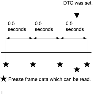
- 3 data sets before the DTC was set
- 1 data sets when the DTC was set
- 1 data set after the DTC was set
- These data sets can be used to simulate the condition of the vehicle around the time the malfunction occurred. The data may assist in identifying the cause of the malfunction, and in judging whether it was temporary or not.
| LIST OF FREEZE FRAME DATA |
| LABEL (Intelligent Tester Display) | Measurement Item | Diagnostic Note |
| Injector | Injector | - |
| IGN Advance | Ignition advance | - |
| Calculate Load | Calculate load | Calculated load by ECM |
| Vehicle Load | Vehicle load | - |
| MAF | Mass air flow volume | If value approximately 0.0 g/s:
|
| Engine Speed | Engine speed | - |
| Vehicle Speed | Vehicle speed | Speed indicated on speedometer |
| Coolant Temp | Engine coolant temperature | If value -40°C (-40°F), sensor circuit open If value 140°C (284°F), sensor circuit shorted |
| Intake Air | Intake air temperature | If value -40°C (-40°F), sensor circuit open If value 140°C (284°F), sensor circuit shorted |
| Air-Fuel Ratio | Air-fuel ratio | - |
| Ambient Temperature | Ambient temperature | - |
| Purge Density Learn Value | Learning value of purge density | - |
| Purge Flow | Purge flow | - |
| EVAP (Purge) VSV | EVAP VSV duty ratio | - |
| Knock Correct Learn Value | Correction learning value of knocking | - |
| Knock Feedback Value | Feedback value of knocking | - |
| Accelerator Position No. 1 | Absolute accelerator pedal position No. 1 | - |
| Accelerator Position No. 2 | Absolute accelerator pedal position No. 2 | - |
| Throttle Position | Throttle position | Read value with engine switch on (IG) (do not start engine) |
| Throttle Sensor Position | Throttle sensor positioning | Read value with engine switch on (IG) (do not start engine) |
| Throttle Sensor Position #2 | Throttle sensor positioning #2 | - |
| Throttle Motor | Throttle motor | - |
| O2S B1 S1 | Heated oxygen sensor output | Performing Inj Vol or Control function of Active Test enables technician to check output voltage of sensor |
| O2S B1 S2 | Heated oxygen sensor output | Performing Inj Vol or Control function of Active Test enables technician to check output voltage of sensor |
| O2S B2 S1 | Heated oxygen sensor output | Performing Inj Vol or Control function of Active Test enables technician to check output voltage of sensor |
| O2S B2 S2 | Heated oxygen sensor output | Performing Inj Vol or Control function of Active Test enables technician to check output voltage of sensor |
| Total FT #1 | Total fuel trim | - |
| Total FT #2 | Total fuel trim | - |
| Short FT #1 | Short-term fuel trim | Short-term fuel compensation used to maintain air-fuel ratio at stoichiometric air-fuel ratio |
| Long FT #1 | Long-term fuel trim | Overall fuel compensation carried out in long-term to compensate a continual deviation of short-term fuel trim from central valve |
| Short FT #2 | Short-term fuel trim | Short-term fuel compensation used to maintain air-fuel ratio at stoichiometric air-fuel ratio |
| Long FT #2 | Long-term fuel trim | Overall fuel compensation carried out in long-term to compensate a continual deviation of short-term fuel trim from central valve |
| Fuel System Status (Bank 1) | Fuel system status (bank 1) |
|
| Fuel System Status (Bank 2) | Fuel system status (bank 2) |
|
| O2FT B1 S1 | Fuel trim at heated oxygen sensor | Same as Short FT #1 |
| O2FT B1 S2 | Fuel trim at heated oxygen sensor | Same as Short FT #1 |
| O2FT B2 S1 | Fuel trim at heated oxygen sensor | Same as Short FT #1 |
| O2FT B2 S2 | Fuel trim at heated oxygen sensor | Same as Short FT #1 |
| O2 LR B1 S1* | Heated oxygen sensor response time (Lean to Rich) | - |
| O2 LR B2 S1* | Heated oxygen sensor response time (Lean to Rich) | - |
| O2 RL B1 S1* | Heated oxygen sensor response time (Rich to Lean) | - |
| O2 RL B2 S1* | Heated oxygen sensor response time (Rich to Lean) | - |
| Catalyst Temp (B1 S1)* | Catalyst temperature | - |
| Catalyst Temp (B2 S1)* | Catalyst temperature | - |
| Catalyst Temp (B1 S2)* | Catalyst temperature | - |
| Catalyst Temp (B2 S2)* | Catalyst temperature | - |
| Initial Engine Coolant Temp | Initial engine coolant temperature | - |
| Initial Intake Air Temp | Initial intake air temperature | - |
| Injection Volume (Cylinder 1) | Injection volume | - |
| ACC Relay | ACC relay | - |
| Starter Relay | Starter relay | - |
| Starter Signal | Starter signal | - |
| Starter Control | Starter control | - |
| Closed Throttle Position SW | Closed throttle position switch | - |
| A/C Signal | A/C signal | - |
| Neutral Position SW Signal | Neutral position switch signal | - |
| Electrical Load Signal | Electrical load signal | - |
| Stop Light Switch | Stop light switch | - |
| Battery Voltage | Battery voltage | - |
| Fuel Pump Speed Control | Fuel pump speed control status | - |
| ACIS VSV | Vacuum switching valve (for ACIS) | - |
| VVT Control Status (Bank 2) | VVT control status (bank 2) | - |
| EVAP Purge VSV | VSV for EVAP | - |
| Fuel Pump/Speed Status | Fuel pump/speed status | - |
| VVT Control Status (Bank 1) | VVT control status (bank 1) | - |
| Electric Fan Motor | Electric fan motor | - |
| TC and TE1 | TC and TE1 terminal of DLC3 | - |
| Idle Fuel Cut Prohibit | Idle fuel cut prohibit | - |
| VVT Aim Angle (Bank 1) | VVT aim angle (bank 1) | - |
| VVT Change Angle (Bank 1) | VVT change angle (bank 1) | - |
| VVT OCV Duty (Bank 1) | VVT OCV operation duty | - |
| VVT Aim Angle (Bank 2) | VVT aim angle (bank 2) | - |
| VVT Change Angle (Bank 2) | VVT change angle (bank 2) | - |
| VVT OCV Duty (Bank 2) | VVT OCV operation duty (bank 2) | - |
| Idle Fuel Cut | Idle fuel cut | ON: when throttle valve fully closed and engine speed over 1,500 rpm |
| FC TAU | FC TAU | Fuel cut being performed under very light load to prevent engine combustion from becoming incomplete |
| Ignition* | Ignition | - |
| Cylinder #1 Misfire Rate* | Cylinder #1 misfire rate | Displayed only during idling |
| Cylinder #2 Misfire Rate* | Cylinder #2 misfire rate | Displayed only during idling |
| Cylinder #3 Misfire Rate* | Cylinder #3 misfire rate | Displayed only during idling |
| Cylinder #4 Misfire Rate* | Cylinder #4 misfire rate | Displayed only during idling |
| Cylinder #5 Misfire Rate* | Cylinder #5 misfire rate | Displayed only during idling |
| Cylinder #6 Misfire Rate* | Cylinder #6 misfire rate | Displayed only during idling |
| Cylinder #7 Misfire Rate* | Cylinder #7 misfire rate | Displayed only during idling |
| Cylinder #8 Misfire Rate* | Cylinder #8 misfire rate | Displayed only during idling |
| All Cylinder Misfire Rate* | All cylinder misfire rate | Displayed only during idling |
| Misfire RPM* | Misfire RPM | - |
| Misfire Load* | Misfired load | - |
| Misfire Margin* | Misfire monitoring | - |
| Engine Run Time | Accumulated engine running time | - |
| Time after DTC Cleared | Cumulative time after DTC cleared | - |
| Distance from DTC Cleared | Accumulated distance from DTC cleared | - |
| Warmup Cycle cleared DTC | Warm-up cycle after DTC cleared | - |
| Model Code | Identifying the model code | UZS19# |
| Engine Type | Identifying the engine type | 3UZ-FE |
| Cylinder Number | Identifying the cylinder number | 8 |
| Destination | Identifying the destination | A (America) |
| Model Year | Identifying the model year | 200# |
- HINT:
- *: Except G.C.C.