Winch System -- On-Vehicle Inspection |
| 1. INSPECT REMOTE CONTROL SWITCH ASSEMBLY |
Connect the remote control switch connector.
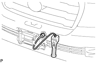 |
Turn the engine switch on (IG) and check that the power indicator light illuminates.
 |
Press the winch control switch, and check that the winch operates.
- NOTICE:
- Be careful not to tighten or strain the winch wire.
Turn the engine switch off.
| 2. REMOVE FRONT FENDER SPLASH SHIELD SUB-ASSEMBLY LH |
Remove the 3 bolts and screw.
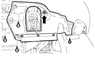 |
Turn the clip indicated by the arrow in the illustration to remove the front fender splash shield sub-assembly LH.
| 3. REMOVE FRONT FENDER SPLASH SHIELD SUB-ASSEMBLY RH |
Remove the 3 bolts and 2 screws.
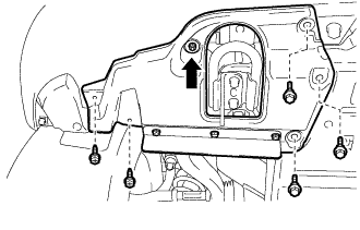 |
Turn the clip indicated by the arrow in the illustration to remove the front fender splash shield sub-assembly RH.
| 4. REMOVE UPPER RADIATOR SUPPORT SEAL |
for Gasoline Engine:
Remove the upper radiator support seal (Click here).
for Diesel Engine:
Remove the upper radiator support seal (Click here).
| 5. REMOVE FRONT BUMPER WINCH COVER SUB-ASSEMBLY |
| 6. REMOVE RADIATOR GRILLE ASSEMBLY |
Put protective tape around the radiator grille assembly.
Text in Illustration *1 Protective Tape
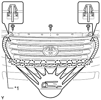 |
Remove the 3 screws.
Detach the 2 clips and 8 claws, and remove the radiator grille assembly.
w/ Wide View Front Monitor System:
Disconnect the connector.
| 7. REMOVE FRONT BUMPER COVER |
Put protective tape around the bumper cover.
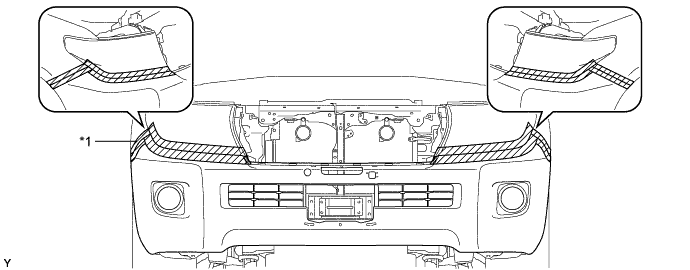
Text in Illustration *1 Protective Tape - -
Using a T30 "TORX" socket, remove the 6 screws.
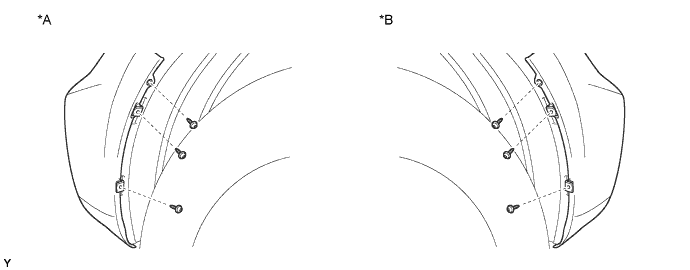
Text in Illustration *A LH Side *B RH Side
Remove the 3 clips, 4 screws and 4 bolts.
Detach the 10 claws.
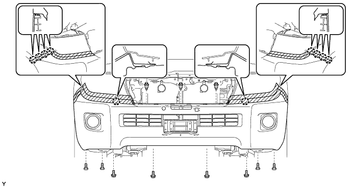
Disconnect the winch control wire connector and remove the front bumper cover.
w/ Fog Light:
Disconnect the No. 4 engine room wire connector and remove the front bumper cover.
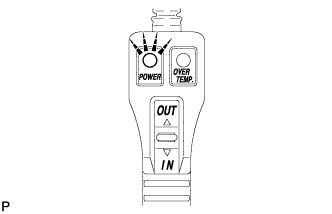
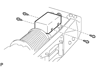
| 8. INSPECT OVERHEAT TEMPERATURE INDICATOR |
Remove the 4 screws and cover.
 |
Disconnect the motor relay connector.
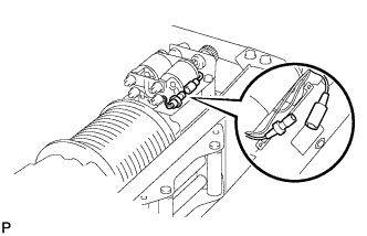 |
Remove the 2 nuts.
 |
Pull the bumper side winch control wire out of the bumper.
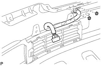
Connect the bumper side winch control wire connector to the vehicle side winch control wire connector.
Connect the bumper side winch control wire connector to the winch control switch connector.
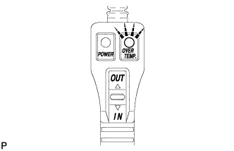
Turn the engine switch on (IG) and check that the overheat temperature indicator light illuminates and the buzzer sounds.
 |
Turn the engine switch off.
Disconnect the bumper side winch control wire connector from the winch control switch connector.
Disconnect the bumper side winch control wire connector from the vehicle side winch control wire connector.
Pass the bumper side winch control wire through the bumper.
Install the 2 nuts.
|
Connect the motor relay connector.
|
Install the cover with the 4 screws.
|
| 9. INSTALL FRONT BUMPER COVER |
w/ Fog Light:
Connect the No. 4 engine room wire connector.
Connect the winch control wire connector and attach the 10 claws to install the front bumper cover.
Install the 3 clips, 4 screws and 4 bolts.
Using a T30 "TORX" socket, install the 6 screws.
| 10. INSTALL RADIATOR GRILLE ASSEMBLY |
w/ Wide View Front Monitor System:
Connect the connector.
Attach the 2 clips and 8 claws to install the radiator grille assembly.
Install the 3 screws.
| 11. INSTALL FRONT BUMPER WINCH COVER SUB-ASSEMBLY |
| 12. INSTALL UPPER RADIATOR SUPPORT SEAL |
for Gasoline Engine:
Install the upper radiator support seal (Click here).
for Diesel Engine:
Install the upper radiator support seal (Click here).
| 13. INSTALL FRONT FENDER SPLASH SHIELD SUB-ASSEMBLY RH |
Push in the clip to install the front fender splash shield sub-assembly RH.
Install the 3 bolts and 2 screws.
| 14. INSTALL FRONT FENDER SPLASH SHIELD SUB-ASSEMBLY LH |
Push in the clip to install the front fender splash shield sub-assembly LH.
Install the 3 bolts and screw.