DISCONNECT CABLE FROM NEGATIVE BATTERY TERMINAL (w/ Navigation System)
REMOVE CENTER NO. 1 INSTRUMENT CLUSTER FINISH PANEL (w/o Audio)
REMOVE CLOCK ASSEMBLY (for Radio and Display Type (Hazard Warning Switch))
REMOVE MULTI-DISPLAY ASSEMBLY (w/ Navigation System (Hazard Warning Switch))
Hazard Warning Switch -- Removal |
- HINT:
- Use the same procedure for RHD and LHD vehicles.
- The procedure listed below is for LHD vehicles.
| 1. PRECAUTION |
- NOTICE:
- After turning the ignition switch off, waiting time may be required before disconnecting the cable from the negative (-) battery terminal. Therefore, make sure to read the disconnecting the cable from the negative (- ) battery terminal notices before proceeding with work (Click here).
| 2. DISCONNECT CABLE FROM NEGATIVE BATTERY TERMINAL (w/ Navigation System) |
- NOTICE:
- When disconnecting the cable, some systems need to be initialized after the cable is reconnected (Click here).
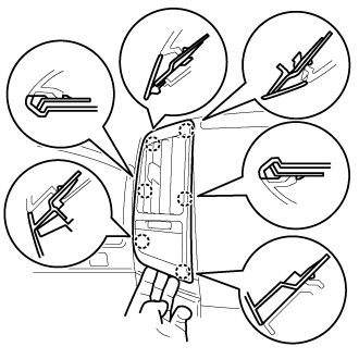
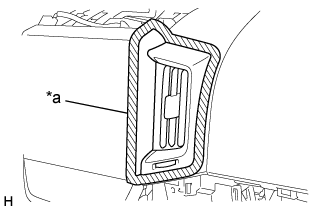
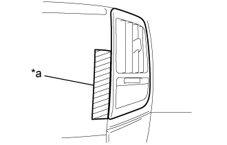
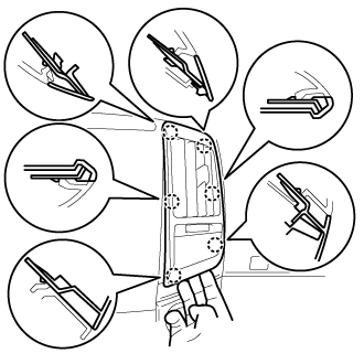
| 3. REMOVE NO. 1 SPEAKER OPENING COVER ASSEMBLY |
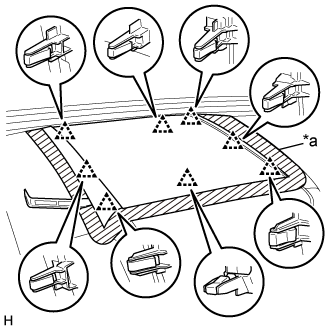 |
Put protective tape around the No. 1 speaker opening cover assembly.
Text in Illustration *a Protective Tape
Using a moulding remover A, detach the 8 clips and remove the No. 1 speaker opening cover assembly.
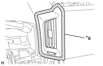
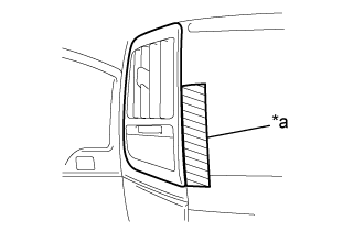
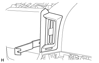
| 4. REMOVE NO. 3 INSTRUMENT PANEL REGISTER ASSEMBLY |
for Type A:
Put protective tape around the No. 3 instrument panel register assembly.
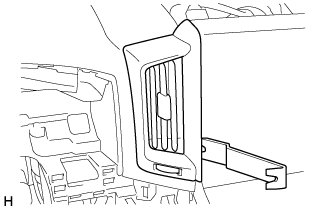
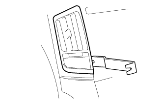
Text in Illustration *a Protective Tape Using moulding remover B, raise the No. 3 instrument panel register assembly.
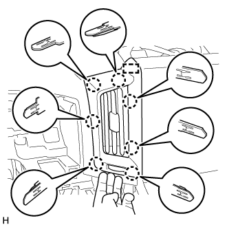
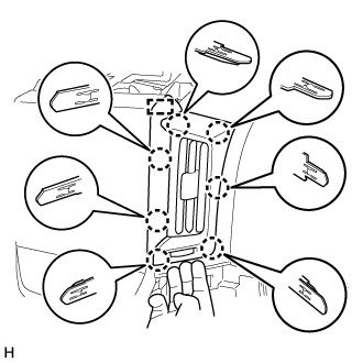
Pull the No. 3 instrument panel register assembly by hand to detach the 7 claws and guide and remove the No. 3 instrument panel register assembly.
for Type B:
Put protective tape around the No. 3 instrument panel register assembly.
Text in Illustration *a Protective Tape Using moulding remover B, raise the No. 3 instrument panel register assembly.
Pull the No. 3 instrument panel register assembly by hand to detach the 6 claws and remove the No. 3 instrument panel register assembly.
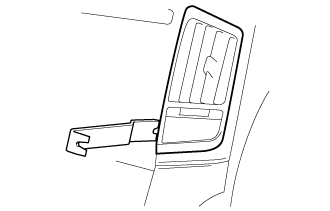
| 5. REMOVE NO. 4 INSTRUMENT PANEL REGISTER ASSEMBLY |
for Type A:
Put protective tape around the No. 3 instrument panel register assembly.
Text in Illustration *a Protective Tape Using moulding remover B, raise the No. 3 instrument panel register assembly.
Pull the No. 3 instrument panel register assembly by hand to detach the 7 claws and guide and remove the No. 3 instrument panel register assembly.
for Type B:
Put protective tape around the No. 3 instrument panel register assembly.
Text in Illustration *a Protective Tape Using moulding remover B, raise the No. 3 instrument panel register assembly.
Pull the No. 3 instrument panel register assembly by hand to detach the 6 claws and remove the No. 3 instrument panel register assembly.
| 6. REMOVE CENTER NO. 1 INSTRUMENT CLUSTER FINISH PANEL (w/o Audio) |
for Type A:
Detach the 8 claws and 3 clips.
Disconnect the connectors and remove the No. 1 center instrument cluster finish panel.
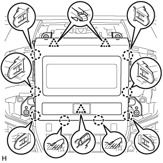
for Type B:
Detach the 10 claws.
Disconnect the connectors and remove the No. 1 center instrument cluster finish panel.
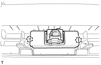
| 7. REMOVE HAZARD WARNING SIGNAL SWITCH ASSEMBLY (w/o Audio) |
Detach the 2 claws and remove the hazard warning signal switch assembly from the center No. 1 instrument cluster finish panel.
 |
| 8. REMOVE RADIO RECEIVER ASSEMBLY (for Radio and Display Type) |
Remove the 2 screws and 2 bolts.
 |
Pull the radio and display receiver assembly with bracket to detach the 6 claws and 2 clips on the backside of the radio and display receiver assembly with bracket.
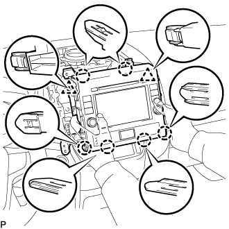 |
Disconnect the connectors and remove the radio and display receiver assembly with bracket.
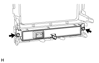
| 9. REMOVE CLOCK ASSEMBLY (for Radio and Display Type (Hazard Warning Switch)) |
Remove the 2 screws and clock assembly.
 |
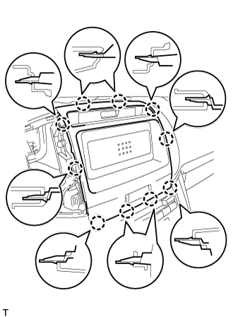
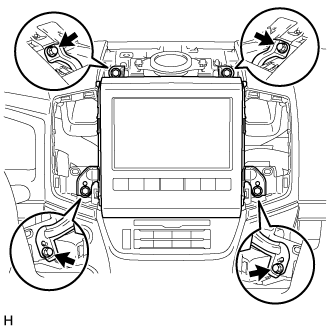
| 10. REMOVE MULTI-DISPLAY ASSEMBLY (w/ Navigation System (Hazard Warning Switch)) |
Remove the 2 bolts and 2 screws.
 |
Pull the multi-display assembly to detach the 8 claws on the backside of the multi-display assembly and remove it.
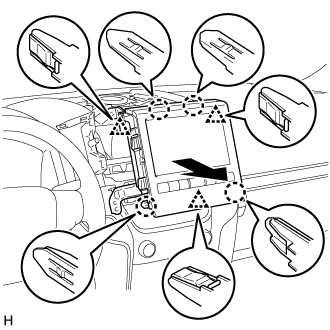 |
Disconnect each connector.