Lighting System Engine Switch Illumination Circuit
DESCRIPTION
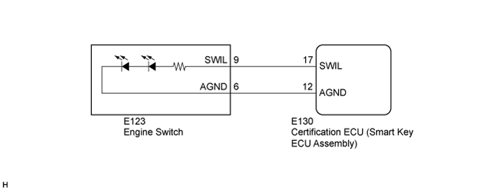
WIRING DIAGRAM
INSPECTION PROCEDURE
INSPECT ENGINE SWITCH
CHECK HARNESS AND CONNECTOR (ENGINE SWITCH - MAIN BODY ECU AND BODY GROUND)
LIGHTING SYSTEM - Engine Switch Illumination Circuit |
DESCRIPTION
The illuminated entry system controls the engine switch illumination.
WIRING DIAGRAM
INSPECTION PROCEDURE
Remove the engine switch.
- for 1UR-FE (Click here).
- for 1VD-FTV (Click here).
- for 1GR-FE (Click here).
Inspect the engine switch.
- for 1UR-FE (Click here).
- for 1VD-FTV (Click here).
- for 1GR-FE (Click here).
ResultResult
| Proceed to
|
OK
| A
|
NG (for 1UR-FE)
| B
|
NG (for 1VD-FTV)
| C
|
NG (for 1GR-FE)
| D
|
| 2.CHECK HARNESS AND CONNECTOR (ENGINE SWITCH - MAIN BODY ECU AND BODY GROUND) |
Disconnect the E123 engine switch connector.
Disconnect the E130 certification ECU (smart key ECU assembly) connector.
Measure the resistance according to the value(s) in the table below.
- Standard Resistance:
Tester Connection
| Condition
| Specified Condition
|
E123-9 (SWIL) - E130-17 (SWIL)
| Always
| Below 1 Ω
|
E123-6 (AGND) - E130-12 (AGND)
| Always
| Below 1 Ω
|
E123-9 (SWIL) or - E130-17 (SWIL) - Body ground
| Always
| 10 kΩ or higher
|
E123-6 (AGND) - E130-12 (AGND) - Body ground
| Always
| 10 kΩ or higher
|
| | REPAIR OR REPLACE HARNESS OR CONNECTOR |
|
|
| OK |
|
|
|
| REPLACE MAIN BODY ECU (MULTIPLEX NETWORK BODY ECU) |
|