DESCRIPTION
WIRING DIAGRAM
INSPECTION PROCEDURE
READ VALUE USING GTS (DOOR COURTESY LIGHT SWITCH)
CHECK DOOR COURTESY LIGHT SWITCH
INSPECT FRONT DOOR COURTESY LIGHT SWITCH LH
CHECK HARNESS AND CONNECTOR (FRONT DOOR COURTESY LIGHT SWITCH LH - MAIN BODY ECU (MULTIPLEX NETWORK BODY ECU))
INSPECT FRONT DOOR COURTESY LIGHT SWITCH RH
CHECK HARNESS AND CONNECTOR (FRONT DOOR COURTESY LIGHT SWITCH RH - MAIN BODY ECU (MULTIPLEX NETWORK BODY ECU))
INSPECT REAR DOOR COURTESY LIGHT SWITCH LH
CHECK HARNESS AND CONNECTOR (REAR DOOR COURTESY LIGHT SWITCH LH - COWL SIDE JUNCTION BLOCK LH)
INSPECT REAR DOOR COURTESY LIGHT SWITCH RH
CHECK HARNESS AND CONNECTOR (REAR DOOR COURTESY LIGHT SWITCH RH - COWL SIDE JUNCTION BLOCK LH)
INSPECT VEHICLE TYPE
INSPECT BACK DOOR WITH MOTOR LOCK ASSEMBLY
CHECK HARNESS AND CONNECTOR (BACK DOOR WITH MOTOR LOCK ASSEMBLY - COWL SIDE JUNCTION BLOCK LH AND BODY GROUND)
INSPECT BACK DOOR LOCK ASSEMBLY
CHECK HARNESS AND CONNECTOR (BACK DOOR LOCK ASSEMBLY - COWL SIDE JUNCTION BLOCK LH AND BODY GROUND)
CHECK COWL SIDE JUNCTION BLOCK LH
CHECK COWL SIDE JUNCTION BLOCK LH
CHECK COWL SIDE JUNCTION BLOCK LH
LIGHTING SYSTEM - Door Courtesy Switch Circuit |
DESCRIPTION
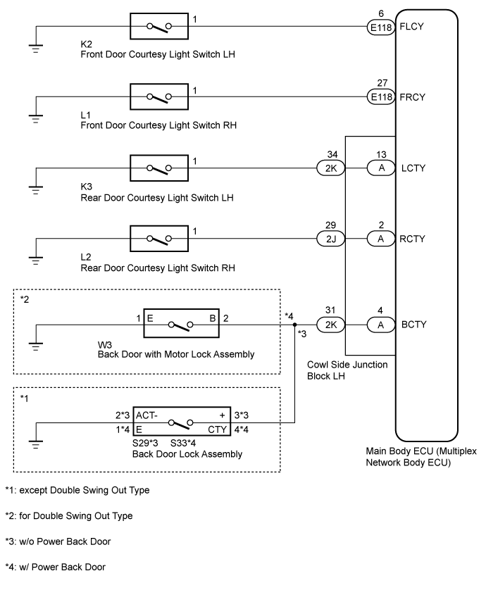
The main body ECU receives a door open/closed signal from each door courtesy light switch.
WIRING DIAGRAM
INSPECTION PROCEDURE
| 1.READ VALUE USING GTS (DOOR COURTESY LIGHT SWITCH) |
Using the GTS, read the Data List (Click here).
Main BodyTester Display
| Measurement Item/Range
| Normal Condition
| Diagnostic Note
|
D Door Courtesy SW
| Front door courtesy light switch LH signal / ON or OFF
| ON: Front door courtesy light switch LH on
OFF: Front door courtesy light switch LH off
| -
|
P Door Courtesy SW
| Front door courtesy light switch RH signal / ON or OFF
| ON: Front door courtesy light switch RH on
OFF: Front door courtesy light switch RH off
| -
|
RL Door Courtesy SW
| Rear door courtesy light switch LH signal / ON or OFF
| ON: Rear door courtesy light switch LH on
OFF: Rear door courtesy light switch LH off
| -
|
RR Door Courtesy SW
| Rear door courtesy light switch RH signal / ON or OFF
| ON: Rear door courtesy light switch RH on
OFF: Rear door courtesy light switch RH off
| -
|
Back Door Courtesy SW
| Back door courtesy light switch signal / ON or OFF
| ON: Back door courtesy light switch on
OFF: Back door courtesy light switch off
| -
|
- OK:
- Door courtesy light switch on/off
| OK |
|
|
|
| PROCEED TO NEXT SUSPECTED AREA SHOWN IN PROBLEM SYMPTOMS TABLE (Click here) |
|
| 2.CHECK DOOR COURTESY LIGHT SWITCH |
ResultResult
| Proceed to
|
Front door courtesy light switch LH does not operate
| A
|
Front door courtesy light switch RH does not operate
| B
|
Rear door courtesy light switch LH does not operate
| C
|
Rear door courtesy light switch RH does not operate
| D
|
Back door courtesy light switch does not operate
| E
|
| 3.INSPECT FRONT DOOR COURTESY LIGHT SWITCH LH |
Remove the front door courtesy light switch LH (Click here).
Inspect the front door courtesy light switch LH (Click here).
| | REPLACE FRONT DOOR COURTESY LIGHT SWITCH LH (Click here) |
|
|
| 4.CHECK HARNESS AND CONNECTOR (FRONT DOOR COURTESY LIGHT SWITCH LH - MAIN BODY ECU (MULTIPLEX NETWORK BODY ECU)) |
Disconnect the K2 front door courtesy light switch LH connector.
Disconnect the E118 main body ECU connector.
Measure the resistance according to the value(s) in the table below.
- Standard Resistance:
Tester Connection
| Condition
| Specified Condition
|
K2-1 - E118-6 (FLCY)
| Always
| Below 1 Ω
|
K2-1 - Body ground
| Always
| 10 kΩ or higher
|
| | REPAIR OR REPLACE HARNESS OR CONNECTOR |
|
|
| OK |
|
|
|
| REPLACE MAIN BODY ECU (MULTIPLEX NETWORK BODY ECU) |
|
| 5.INSPECT FRONT DOOR COURTESY LIGHT SWITCH RH |
Remove the front door courtesy light switch RH (Click here).
Inspect the front door courtesy light switch RH (Click here).
| | REPLACE FRONT DOOR COURTESY LIGHT SWITCH RH (Click here) |
|
|
| 6.CHECK HARNESS AND CONNECTOR (FRONT DOOR COURTESY LIGHT SWITCH RH - MAIN BODY ECU (MULTIPLEX NETWORK BODY ECU)) |
Disconnect the L1 front door courtesy light switch RH switch connector.
Disconnect the E118 main body ECU connector.
Measure the resistance according to the value(s) in the table below.
- Standard Resistance:
Tester Connection
| Condition
| Specified Condition
|
L1-1 - E118-27 (FRCY)
| Always
| Below 1 Ω
|
L1-1 - Body ground
| Always
| 10 kΩ or higher
|
| | REPAIR OR REPLACE HARNESS OR CONNECTOR |
|
|
| OK |
|
|
|
| REPLACE MAIN BODY ECU (MULTIPLEX NETWORK BODY ECU) |
|
| 7.INSPECT REAR DOOR COURTESY LIGHT SWITCH LH |
Remove the rear door courtesy light switch LH (Click here).
Inspect the rear door courtesy light switch LH (Click here).
| | REPLACE REAR DOOR COURTESY LIGHT SWITCH LH (Click here) |
|
|
| 8.CHECK HARNESS AND CONNECTOR (REAR DOOR COURTESY LIGHT SWITCH LH - COWL SIDE JUNCTION BLOCK LH) |
Disconnect the 2K cowl side junction block LH connector.
Disconnect the K3 rear door courtesy light switch LH connector.
Measure the resistance according to the value(s) in the table below.
- Standard Resistance:
Tester Connection
| Condition
| Specified Condition
|
K3-1 - 2K-34 (LCTY)
| Always
| Below 1 Ω
|
K3-1 - Body ground
| Always
| 10 kΩ or higher
|
| |
|
| | REPAIR OR REPLACE HARNESS OR CONNECTOR |
|
|
| 9.INSPECT REAR DOOR COURTESY LIGHT SWITCH RH |
Remove the rear door courtesy light switch RH (Click here).
Inspect the rear door courtesy light switch RH (Click here).
| | REPLACE REAR DOOR COURTESY LIGHT SWITCH RH (Click here) |
|
|
| 10.CHECK HARNESS AND CONNECTOR (REAR DOOR COURTESY LIGHT SWITCH RH - COWL SIDE JUNCTION BLOCK LH) |
Disconnect the L2 rear door courtesy light switch RH connector.
Disconnect the 2J cowl side junction block LH connector.
Measure the resistance according to the value(s) in the table below.
- Standard Resistance:
Tester Connection
| Condition
| Specified Condition
|
L2-1 - 2J-29 (RCTY)
| Always
| Below 1 Ω
|
L2-1 - Body ground
| Always
| 10 kΩ or higher
|
| |
|
| | REPAIR OR REPLACE HARNESS OR CONNECTOR |
|
|
Check the vehicle type.
ResultResult
| Proceed to
|
for Double Swing Out Type
| A
|
except Double Swing Out Type
| B
|
| 12.INSPECT BACK DOOR WITH MOTOR LOCK ASSEMBLY |
Remove the back door with motor lock assembly (Click here).
Inspect the back door with motor lock assembly (Click here).
| | REPLACE BACK DOOR WITH MOTOR LOCK ASSEMBLY (Click here) |
|
|
| 13.CHECK HARNESS AND CONNECTOR (BACK DOOR WITH MOTOR LOCK ASSEMBLY - COWL SIDE JUNCTION BLOCK LH AND BODY GROUND) |
Disconnect 2K cowl side junction block LH connector.
Disconnect W3 back door with motor lock connector.
Measure the resistance according to the value(s) in the table below.
- Standard Resistance:
Tester Connection
| Condition
| Specified Condition
|
W3-2 (B) - 2K-31 (BCTY)
| Always
| Below 1 Ω
|
W3-1 (E) - Body ground
|
W3-2 (B) - Body ground
| Always
| 10 kΩ or higher
|
| |
|
| | REPAIR OR REPLACE HARNESS OR CONNECTOR |
|
|
| 14.INSPECT BACK DOOR LOCK ASSEMBLY |
Remove the back door lock (Click here).
Inspect the back door lock (Click here).
| 15.CHECK HARNESS AND CONNECTOR (BACK DOOR LOCK ASSEMBLY - COWL SIDE JUNCTION BLOCK LH AND BODY GROUND) |
Disconnect the 2K cowl side junction block LH connector.
w/o Power Back Door:
Disconnect the S29 back door lock connector.
Measure the resistance according to the value(s) in the table below.
- Standard Resistance:
Tester Connection
| Condition
| Specified Condition
|
S29-3 (+) - 2K-31 (BCTY)
| Always
| Below 1 Ω
|
S29-2 (ACT-) - Body ground
|
S29-3 (+) - Body ground
| Always
| 10 kΩ or higher
|
w/ Power Back Door:
Disconnect the S33 back door lock connector.
Measure the resistance according to the value(s) in the table below.
- Standard Resistance:
Tester Connection
| Condition
| Specified Condition
|
S33-4 (CTY) - 2K-31 (BCTY)
| Always
| Below 1 Ω
|
S33-1 (E) - Body ground
|
S33-4 (CTY) - Body ground
| Always
| 10 kΩ or higher
|
| |
|
| | REPAIR OR REPLACE HARNESS OR CONNECTOR |
|
|
| 16.CHECK COWL SIDE JUNCTION BLOCK LH |
Remove the cowl side junction block LH.
Remove the main body ECU from the cowl side junction block LH
Measure the resistance according to the value(s) in the table below.
- Standard Resistance:
Tester Connection
| Condition
| Specified Condition
|
2K-34 - A-13
| Always
| Below 1 Ω
|
2K-34 - Body ground
| Always
| 10 kΩ or higher
|
| | REPLACE COWL SIDE JUNCTION BLOCK LH |
|
|
| OK |
|
|
|
| REPLACE MAIN BODY ECU (MULTIPLEX NETWORK BODY ECU) |
|
| 17.CHECK COWL SIDE JUNCTION BLOCK LH |
Remove the cowl side junction block LH.
Remove the main body ECU from the cowl side junction block LH
Measure the resistance according to the value(s) in the table below.
- Standard Resistance:
Tester Connection
| Condition
| Specified Condition
|
2J-29 - A-2
| Always
| Below 1 Ω
|
2J-29 - Body ground
| Always
| 10 kΩ or higher
|
| | REPLACE COWL SIDE JUNCTION BLOCK LH |
|
|
| OK |
|
|
|
| REPLACE MAIN BODY ECU (MULTIPLEX NETWORK BODY ECU) |
|
| 18.CHECK COWL SIDE JUNCTION BLOCK LH |
Remove the cowl side junction block LH.
Remove the main body ECU from the cowl side junction block LH
Measure the resistance according to the value(s) in the table below.
- Standard Resistance:
Tester Connection
| Condition
| Specified Condition
|
2K-31 - A-4
| Always
| Below 1 Ω
|
2K-31 - Body ground
| Always
| 10 kΩ or higher
|
| | REPLACE COWL SIDE JUNCTION BLOCK LH |
|
|
| OK |
|
|
|
| REPLACE MAIN BODY ECU (MULTIPLEX NETWORK BODY ECU) |
|