Lighting System -- Terminals Of Ecu |
| CHECK COWL SIDE JUNCTION BLOCK LH, MAIN BODY ECU (MULTIPLEX NET WORK BODY ECU) |
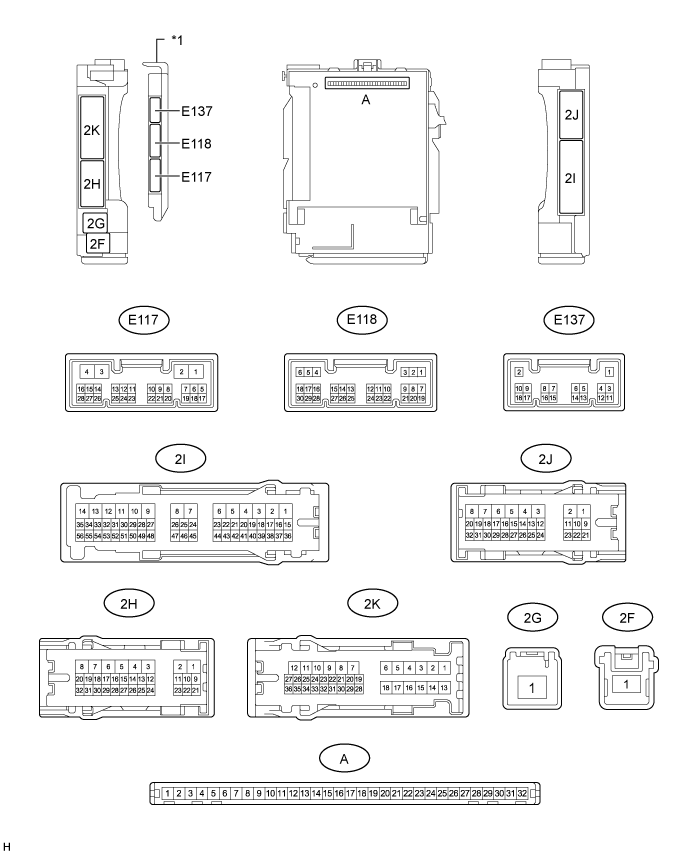
| *1 | Main Body ECU (Multiplex Network Body ECU) | - | - |
Disconnect the E118, 2K and 2J ECU connectors.
Measure the voltage and resistance according to the value(s) in the table below.
Terminal No. (Symbol) Wiring Color Terminal Description Condition Specified Condition A-31 (BECU) - Body ground - Battery power supply Always 11 to 14 V A-30 (ACC) - Body ground - ACC power supply Ignition switch off Below 1 V Ignition switch ON 11 to 14 V A-32 (IG) - Body ground - Ignition power supply Ignition switch off Below 1 V Ignition switch ON 11 to 14 V A-11 (GND1) - Body ground - Ground Always Below 1 Ω 2G-1 (TRLY) - Body ground W - Body ground Taillight power supply Always 11 to 14 V E118-6 (FLCY) - Body ground V - Body ground Front door courtesy light switch LH signal Front door LH open Below 1 Ω V - Body ground Front door courtesy light switch LH signal Front door LH closed 10 kΩ or higher E118-27 (FRCY) - Body ground V - Body ground Front door courtesy light switch RH signal Front door RH open Below 1 Ω V - Body ground Front door courtesy light switch RH signal Front door RH closed 10 kΩ or higher 2K-34 (LCTY) - Body ground BE - Body ground Rear door courtesy light switch LH signal Rear door LH open Below 1 Ω BE - Body ground Rear door courtesy light switch LH signal Rear door LH closed 10 kΩ or higher 2J-29 (RCTY) - Body ground BE - Body ground Rear door courtesy light switch RH signal Rear door RH open Below 1 Ω BE - Body ground Rear door courtesy light switch RH signal Rear door RH closed 10 kΩ or higher 2K-31 (BCTY) - Body ground W - Body ground Back door courtesy light switch signal Back door open Below 1 Ω W - Body ground Back door courtesy light switch signal Back door closed 10 kΩ or higher E118-22 (TAIL) - Body ground B - Body ground Light control switch TAIL signal Light control switch tail Below 1 Ω B - Body ground Light control switch TAIL signal Light control switch except tail 10 kΩ or higher E118-12 (HEAD) - Body ground R- Body ground Light control switch HEAD signal Light control switch head Below 1 Ω R - Body ground Light control switch HEAD signal Light control switch except head 10 kΩ or higher E118-8 (A) - Body ground P - Body ground Light control switch AUTO signal Light control switch AUTO Below 1 Ω P - Body ground Light control switch AUTO signal Light control switch except AUTO 10 kΩ or higher E118-26 (FFOG) - Body ground*1 W - Body ground Front fog light switch signal Front fog light switch on Below 1 Ω W - Body ground Front fog light switch signal Front fog light switch off 10 kΩ or higher E118-23 (RFOG) - Body ground*2 P - Body ground Rear fog light switch signal Rear fog light switch on Below 1 Ω P - Body ground Rear fog light switch signal Rear fog light switch off 10 kΩ or higher E118-24 (HU) - Body ground V - Body ground Dimmer switch high signal Dimmer switch high Below 1 Ω V - Body ground Dimmer switch high signal Dimmer switch except high or flash 10 kΩ or higher E118-10 (HF) - Body ground L - Body ground Dimmer switch flash signal Dimmer switch flash Below 1 Ω L - Body ground Dimmer switch flash Signal Dimmer switch except flash 10 kΩ or higher 2J-30 (ILE) - Body ground G - Body ground*3
SB - Body ground*4Interior light signal Map light on Below 1 Ω G - Body ground*3
SB - Body ground*4Interior light signal Map light off 10 kΩ or higher 2J-11 (DOMR) - Body ground*4 R - Body ground Battery save system (interior light auto cut function) signal Battery save system (interior light auto cut function) operating 11 to 14 V R - Body ground Battery save system (interior light auto cut function) signal Battery save system (interior light auto cut function) not operating Below 1 V - *1: w/ Front Fog Light
- *2: w/ Rear Fog Light
- *3: w/o Door Ajar Warning Buzzer Function
- *4: w/ Door Ajar Warning Buzzer Function
- *1: w/ Front Fog Light
Reconnect the E118, 2K and 2J ECU connectors.
Measure the voltage according to the value(s) in the table below.
Terminal No. (Symbol) Wiring Color Terminal Description Condition Specified Condition 2H-31 (FFGO) - Body ground*1 L - Body ground Front fog light signal Light control switch tail,
front fog light switch onBelow 1 V L - Body ground Front fog light signal Light control switch tail,
front fog light switch off11 to 14 V 2H-30 (HRLY) - Body ground B - Body ground Headlight low beam signal Light control switch head,
dimmer switch lowBelow 1 V B - Body ground Headlight low beam signal Light control switch head,
dimmer switch except low11 to 14 V 2H-28 (DRLE) - Body ground*2 R - Body ground Daytime running light signal Daytime running light on Below 1 V R - Body ground Daytime running light signal Daytime running light off 11 to 14 V E118-1 (DIM) - Body ground B - Body ground Headlight High beam signal Light control switch head,
dimmer switch highBelow 1 V B - Body ground Headlight High beam signal Light control switch head,
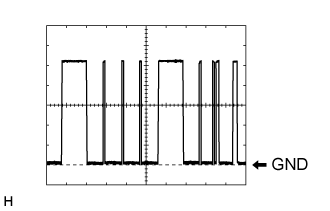
dimmer switch except high11 to 14 V E117-23 (AHBI) - Body ground*3 L - Body ground Auto high beam switch signal input Automatic high beam switch on Below 1 V Automatic high beam switch off 11 to 14 V E118-20 (CLTS) - Body ground R - Body ground Automatic light control sensor signal input Ignition switch off Below 1 V Ignition switch ON, headlight dimmer switch in AUTO position, material which blocks light used to cover and then uncover top of automatic light control sensor Pulse generation
(See waveform 1)- *1: w/ Front Fog Light
- *2: w/ w/ Daytime Running Light
- *3: w/ Automatic High Beam System
- *1: w/ Front Fog Light
Waveform 1
Item Content Terminal No. (Symbol) E118-20 (CLTS) - Body ground Tool Setting 2 V/DIV., 10 ms./DIV. Condition Ignition switch ON, headlight dimmer switch in AUTO position, material which blocks light used to cover and then uncover top of automatic light control sensor
 |
| CHECK COMBINATION METER ASSEMBLY |
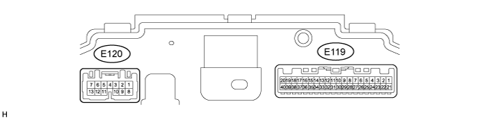
Disconnect the E119 and E120 combination meter connectors.
Measure the voltage and resistance according to the value(s) in the table below.
Terminal No. (Symbol) Wiring Color Terminal Description Condition Specified Condition E119-21 (B) - Body ground V - Body ground IG power supply Ignition switch off Below 1 V Ignition switch ON 11 to 14 V E119-22 (IG+) - Body ground BE - Body ground Ground Ignition switch off → Ignition switch ON Below 1 V → 8.5 to 14 V E120-1 (B) - Body ground P - Body ground Battery Ignition switch off 11 to 14 V E120-11 (HZSW) - Body ground P - Body ground Hazard warning signal switch signal (Output) Ignition switch ON, hazard warning signal switch on 11 to 14 V Ignition switch ON, hazard warning signal switch off Below 1 V E119-20 (ET) - Body ground BR - Body ground Ground Always Below 1 Ω Reconnect the E119 and E120 combination meter connectors.
Measure the voltage according to the value(s) in the table below.
Terminal No. (Symbol) Wiring Color Terminal Description Condition Specified Condition E120-9 (ER) - Body ground B - Body ground RH turn indicator light signal (Input) Ignition switch ON, RH turn signal switch on Below 1 V Ignition switch ON, RH turn signal switch off 11 to 14 V E120-10 (EL) - Body ground L - Body ground LH turn indicator light signal (Input) Ignition switch ON, LH turn signal switch on Below 1 V Ignition switch ON, LH turn signal switch off 11 to 14 V E120-7 (LL) - Body ground L - Body ground LH turn indicator light signal (Output) Ignition switch ON, LH turn indicator light off Below 1 V Ignition switch ON, LH turn indicator light blinking 11 to 14 V ←→ Below 1 V E120-13 (LR) - Body ground R - Body ground RH turn indicator light signal (Output) Ignition switch ON, RH turn indicator light off Below 1 V Ignition switch ON, LH turn indicator light blinking 11 to 14 V ←→ Below 1 V
| CHECK HEADLIGHT LEVELING ECU ASSEMBLY (w/ Static Headlight Auto Leveling) |

Disconnect the E109 headlight leveling ECU connector.
Measure the voltage and resistance according to the value(s) in the table below.
If the result is not as specified, there may be a malfunction on the wire harness side.Terminal No. (Symbol) Wiring Color Terminal Description Condition Specified Condition E109-1 (IG) - Body ground G - Body ground Ignition power supply Ignition switch off Below 1 V Ignition switch ON 11 to 14 V E109-9 (E1) - Body ground W-B - Body ground Ground Always Below 1 Ω Reconnect the E109 headlight leveling ECU connector.
Measure the voltage and resistance according to the value(s) in the table below.
Terminal No. (Symbol) Wiring Color Terminal Description Condition Specified Condition E109-10 (RH+) - E109-9 (E1) L - W-B Headlight leveling motor RH power supply Ignition switch off Below 1 V Ignition switch ON 11 to 14 V E109-11 (LH+) - E109-9 (E1) L - W-B Headlight leveling motor LH power supply Ignition switch off Below 1 V Ignition switch ON 11 to 14 V E109-12 (SBR) - E109-21 (SGR) B - G Rear height control sensor power supply Ignition switch off Below 1 V Ignition switch ON 4.75 to 5.25 V E109-17 (RHT) - E109-9 (E1) P - W-B Headlight leveling motor RH operation signal input With low beam headlights on, vehicle height not changed Below 1 V With low beam headlights on, vehicle height changed and maintained for more than 3 seconds 1.0 to 14.4 V E109-18 (LHT) - E109-9 (E1) P - W-B Headlight leveling motor LH operation signal input With low beam headlights on, vehicle height not changed Below 1 V With low beam headlights on, vehicle height changed and maintained for more than 3 seconds 1.0 to 14.4 V E109-19 (SHRL) - E109- 21 (SGR) R - G Rear height control sensor signal input Ignition switch off Below 1 V Ignition switch ON 0.5 to 4.5 V E109-21 (SGR) - E109-9 (E1) G - W-B Rear height control sensor ground Always Below 1 Ω E109-23 (RH-) - E109-9 (E1) R - W-B Headlight leveling motor RH ground Always Below 1 Ω E109-24 (LH-) - E109-9 (E1) R - W-B Headlight leveling motor LH ground Always Below 1 Ω
| CHECK HEADLIGHT SWIVEL ECU ASSEMBLY (w/ Dynamic Headlight Auto Leveling) |

Disconnect the E101 headlight swivel ECU connector.
Measure the voltage and resistance according to the value(s) in the table below.
If the result is not as specified, there may be a malfunction on the wire harness side.Terminal No. (Symbol) Wiring Color Terminal Description Condition Specified Condition E101-14 (IGS) - Body ground R - Body ground Ignition power supply Ignition switch off Below 1 V Ignition switch ON 11 to 14 V E101-15 (IG) - Body ground G - Body ground Ignition power supply Ignition switch off Below 1 V Ignition switch ON 11 to 14 V E101-22 (E1) - Body ground W-B - Body ground Ground Always Below 1 Ω Reconnect the E101 headlight swivel ECU connector.
Measure the voltage and resistance according to the value(s) in the table below.
Terminal No. (Symbol) Wiring Color Terminal Description Condition Specified Condition E101-2 (SMBR) - E101-22 (E1) L - W-B Headlight leveling motor RH power supply Ignition switch off Below 1 V Ignition switch ON 11 to 14 V E101-11 (SMBL) - E101-22 (E1) L - W-B Headlight leveling motor LH power supply Ignition switch off Below 1 V Ignition switch ON 11 to 14 V E101-18 (SBR) - E101-21 (SGR) B - G Rear height control sensor power supply Ignition switch off Below 1 V Ignition switch ON 4.75 to 5.25 V E101-11 (RH+) - E101-22 (E1) P - W-B Headlight leveling motor RH operation signal input With low beam headlights on, vehicle height not changed Below 1 V With low beam headlights on, vehicle height changed and maintained for more than 3 seconds 1.0 to 14.4 V E101-30 (LH+) - E101-21 (E1) P - W-B Headlight leveling motor LH operation signal input With low beam headlights on, vehicle height not changed Below 1 V With low beam headlights on, vehicle height changed and maintained for more than 3 seconds 1.0 to 14.4 V E101-19 (SHRL) - E101- 21 (SGR) R - G Rear height control sensor signal input Ignition switch off Below 1 V Ignition switch ON 0.5 to 4.5 V E101-21 (SGR) - E101-21 (E1) G - W-B Rear height control sensor ground Always Below 1 Ω E101-26 (RH-) - E101-21 (E1) R - W-B Headlight leveling motor RH ground Always Below 1 Ω E101-27 (LH-) - E101-21 (E1) R - W-B Headlight leveling motor LH ground Always Below 1 Ω
| CHECK NO. 2 MAIN BODY ECU (w/ Side Step Light) |
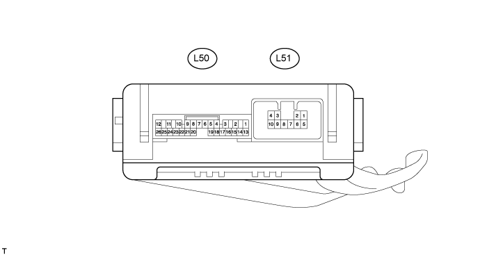
Disconnect the L50 and L51 ECU connectors.
Measure the voltage and resistance according to the value(s) in the table below.
Terminal No. (Symbol) Wiring Color Terminal Description Condition Specified Condition L50-14 (BECU) - Body ground R - Body ground Battery power supply Always 11 to 14 V L50-13 (SIG) - Body ground B - Body ground Ignition power supply Ignition switch off Below 1 V Ignition switch ON 11 to 14 V L50-7 (GND) - Body ground W-B - Body ground Ground Always Below 1 Ω L51-7 (GND) - Body ground W-B - Body ground Ground Always Below 1 Ω - If the result is not as specified, there may be a malfunction on the wire harness side.
- If the result is not as specified, there may be a malfunction on the wire harness side.
Reconnect the L50 and L51 ECU connectors.
Measure the voltage according to the value(s) in the table below.
Terminal No. (Symbol) Wiring Color Terminal Description Condition Specified Condition L50-9 (RBD1) - Body ground L - Body ground Step light LH signal Step light LH on Below 1 V Step light LH off 11 to 14 V L50-21 (RBD2) - Body ground L - Body ground Step light RH signal Step light RH on Below 1 V Step light RH off 11 to 14 V
| CHECK INNER REAR VIEW MIRROR ASSEMBLY (w/o Pre-crash Safety System) |

Disconnect the R16 mirror connector.
Measure the voltage and resistance according to the value(s) in the table below.
Terminal No. (Symbol) Wiring Color Terminal Description Condition Specified Condition R16-1 (IG) - Body ground B - Body ground IG power supply Ignition switch ON 11 to 14 V R16-2 (E) - Body ground W-B - Body ground Ground Always Below 1 Ω R16-9 (CANH) - Body ground G - Body ground CAN communication line Ignition switch ON Pulse generation R16-10 (CANL) - Body ground B - Body ground CAN communication line Ignition switch ON Pulse generation
| FORWARD RECOGNITION CAMERA (w/ Pre-crash Safety System) |