Outer Mirror Switch -- Installation |
- HINT:
- A bolt without a torque specification is shown in the standard bolt chart (Click here).
| 1. INSTALL RETRACTABLE OUTER MIRROR SWITCH (w/ Retract Mirror) |
Attach the 2 claws to install the switch.
| 2. INSTALL OUTER MIRROR SWITCH ASSEMBLY |
Attach the 4 claws to install the switch.
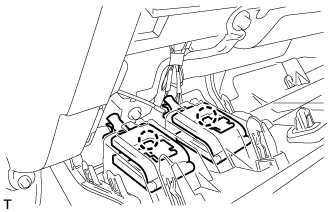
| 3. INSTALL NO. 1 SWITCH HOLE BASE |
 |
Connect the connectors.
Attach the 4 claws to install the No. 1 switch hole base.
| 4. INSTALL LOWER NO. 1 INSTRUMENT PANEL FINISH PANEL |
Connect the connectors.
for Automatic Air Conditioning System:
Attach the 2 claws to install the room temperature sensor.
 |
Attach the 2 claws to connect the 2 control cables.
 |
w/ Driver Side Knee Airbag:
Attach the 16 claws to install the lower No. 1 instrument panel finish panel.
Install the 2 bolts.
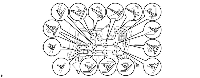
w/o Driver Side Knee Airbag:
Attach the 9 claws to install the lower No. 1 instrument panel finish panel.
Install the 2 bolts.

Attach the 2 claws to close the hole cover.
 |
| 5. INSTALL NO. 1 INSTRUMENT PANEL UNDER COVER SUB-ASSEMBLY (w/ Floor Under Cover) |
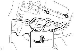 |
Connect the connectors.
Attach the 3 claws to install the No. 1 instrument panel under cover.
Install the 2 screws.
| 6. INSTALL NO. 2 INSTRUMENT CLUSTER FINISH PANEL GARNISH |
Attach the 2 claws to install the No. 2 instrument cluster finish panel garnish.
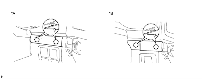
Text in Illustration *A w/ Entry and Start System *B w/o Entry and Start System
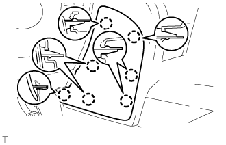
| 7. INSTALL NO. 1 INSTRUMENT CLUSTER FINISH PANEL GARNISH |
 |
Attach the 3 claws to install the No. 1 instrument cluster finish panel garnish.
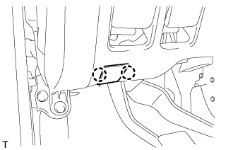
| 8. INSTALL LOWER INSTRUMENT PANEL PAD SUB-ASSEMBLY LH |
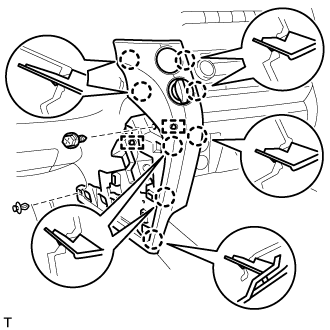 |
Connect the connectors and attach the 2 clamps.
Attach the 8 claws to install the lower instrument panel pad sub-assembly.
Install the clip and screw.
| 9. INSTALL NO. 2 INSTRUMENT PANEL FINISH PANEL CUSHION |
 |
Attach the 7 claws to install the No. 2 instrument panel finish panel cushion.