Outer Rear View Mirror -- Reassembly |
- HINT:
- Use the same procedure for RHD and LHD vehicles.
- The procedure listed below is for LHD vehicles.
- Use the same procedure for the RH and LH sides.
- The procedure listed below is for the LH side.
| 1. INSTALL SIDE TELEVISION CAMERA ASSEMBLY (w/ Multi-terrain Monitor) |
Install the side television camera assembly LH with the 2 screws.
Attach the clamp.
| 2. INSTALL OUTER MIRROR RETRACTOR LH |
Install the support spring
Attach the 6 claws and install the 2 support springs.
Install the 2 screws.

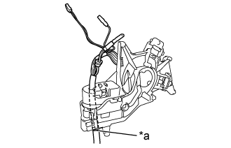
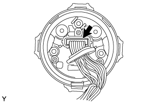
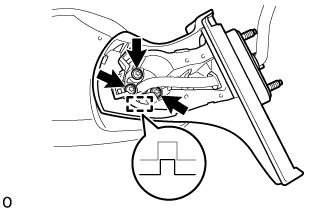
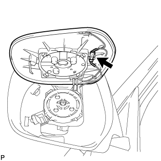
Install the wire harness
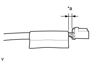
Pass a new wire harness through the motor and frame sub-assembly from the top, and set the marking of the wire harness to the position shown in the illustration.
Text in Illustration *a Marking Connect the connector.
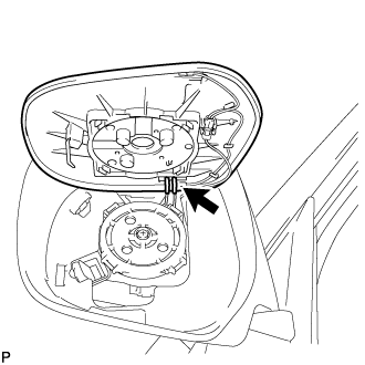
Install the cover.
Attach the clamp.
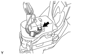
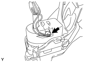
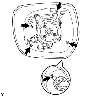
Install the actuator sub-assembly
Connect the connector.
Install the cover and attach the 2 clamps.
Install the actuator sub-assembly with the 3 screws.


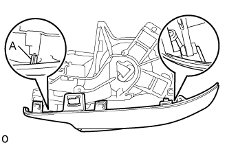
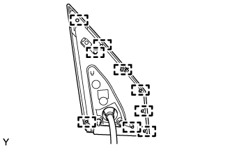
Install the body cover
Attach the 2 guides and body cover.
- NOTICE:
- Be careful not to break the guide shown in the part of the illustration labeled A.
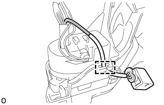
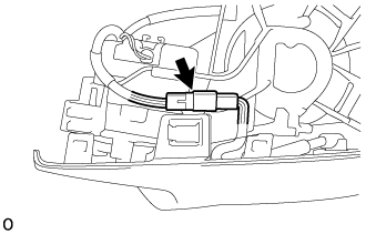
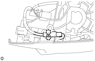
Connect the connector.
Attach the 2 claws and install the connector to the body cover.
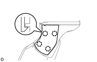
Install the body
Install the body with the 5 screws.
Install the base
Attach the guide.
Using "TORX" socket wrench T25, install the base with 3 new "TORX" screws.
- NOTICE:
- When installing the base, check that the wire harness is not caught between the base and housing. Failure to do so may cause a short circuit.
Pass the wire harness through the base.
Install the lower mirror cover
Attach the 4 claws and install the new lower mirror cover.
Install the gasket
Pass the wire harness through the new gasket.
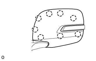
Attach the 9 guides and install the gasket.
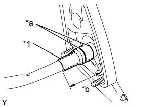
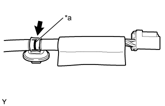
Align the marking on the wire harness with the marking on the end of the wire harness insertion hole of the gasket as shown in the illustration, and wrap them with new vinyl tape starting from the gasket marking.
Text in Illustration *1 New Vinyl Tape *a Marking *b 50 mm (1.9685 in.) - NOTICE:
- If the vinyl tape is wrinkled, water may run down the wire harness and enter the vehicle. Make sure to wind the vinyl tape properly.
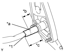
Wrap new vinyl tape as shown in the illustration.
Text in Illustration *1 New Vinyl Tape *a Overlap *b 30 mm (1.1811 in.) *c 50 mm (1.9685 in.)
Install the connector
Set the retainer to the unlock position.
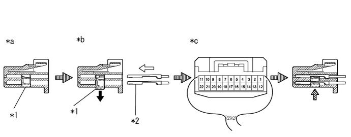
Text in Illustration *1 Retainer *2 Wire Harness Pin *a Retainer Lock Position *b Retainer Unlock Position *c Back View of Wire Harness Connector - -
*A: w/ Blind spot monitor systemWire Harness Connector Terminal 1 2 3 4 5 6 7 8 Wire Harness Color Yellow Green Red / Blue Orange Blue / Black Black / White Purple Red Connector Terminal 9 10 11 12 13 14 15 (*A) 16 Wire Harness Color Brown Red / White Pink Black Blue Green / Red Blue / White Black / Red Connector Terminal 17 18 19 20 21 22 - - Wire Harness Color Black / Green - Sky Blue White Gray Light Green - - - NOTICE:
- When inserting the wire harness pins, compare with the connector that was cut off during removal to verify the insertion positions, and then make sure to insert the pins of the correct wire colors in the correct positions.
- Make sure that the wire harness pins are securely locked in position and cannot be removed.
- The wire harness pins cannot be removed after they have locked into place, so be absolutely certain to insert them in the correct positions.
Push in the wire harness pins from the rear side of the connector until they lock into position.
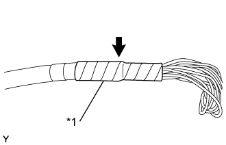
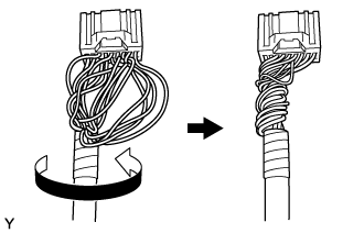
Twist the wire harness as shown in the illustration.
Wrap with new vinyl tape.
Text in Illustration *1 New Vinyl Tape Twist the wire harness as shown in the illustration.
Install a new vinyl sheet in the position shown in the illustration.
Text in Illustration *a 5 mm (0.1969 in.) Install a new wire harness clamp at the marking shown in the illustration.
Text in Illustration *a Marking
| 3. INSTALL SIDE TURN SIGNAL LIGHT ASSEMBLY LH |
Connect the connector.
Install the light with the 3 screws.
| 4. INSTALL OUTER MIRROR COVER LH |
Install the outer mirror cover LH.
Insert the rib on the outer edge of the cover into the groove of the mirror body.
- NOTICE:
- Do not scratch the turn light.
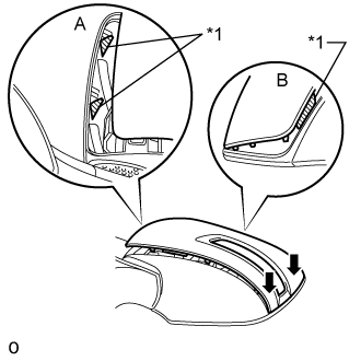
Text in Illustration *1 Rib Confirm that the cover and mirror body are aligned properly, and then push the outer end of the cover to attach the outer claws.
- NOTICE:
- Make sure that the upper ribs of the cover shown in part A of the illustration are properly attached to the mirror body.
- Make sure that the ribs of the mirror body shown in part B of the illustration are not protruding from the cover.
Text in Illustration *1 Rib While making sure that the rib of the cover fits properly into the groove of the mirror body, squeeze the inner end of the cover and the mirror body together to attach the inner claws.


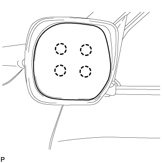
Push on the cover at the locations of the 8 claws to confirm that the claws are attached properly.
 |
Check that there is no gap between the cover and mirror body.
- HINT:
- If there is a gap between the cover and body, noise will occur during driving.
| 5. INSTALL OUTER MIRROR LH |
w/ Blind Spot Monitor System:
Connect the connector.
 |
w/ EC Mirror:
Connect the connector.
 |
w/ Mirror Heater:
Connect the 2 connectors.
 |
Attach the 4 claws to install the outer mirror LH.
 |