Power Mirror Control System (W/ Retract Mirror) Power Mirror Cannot Be Adjusted With Power Mirror Switch
DESCRIPTION
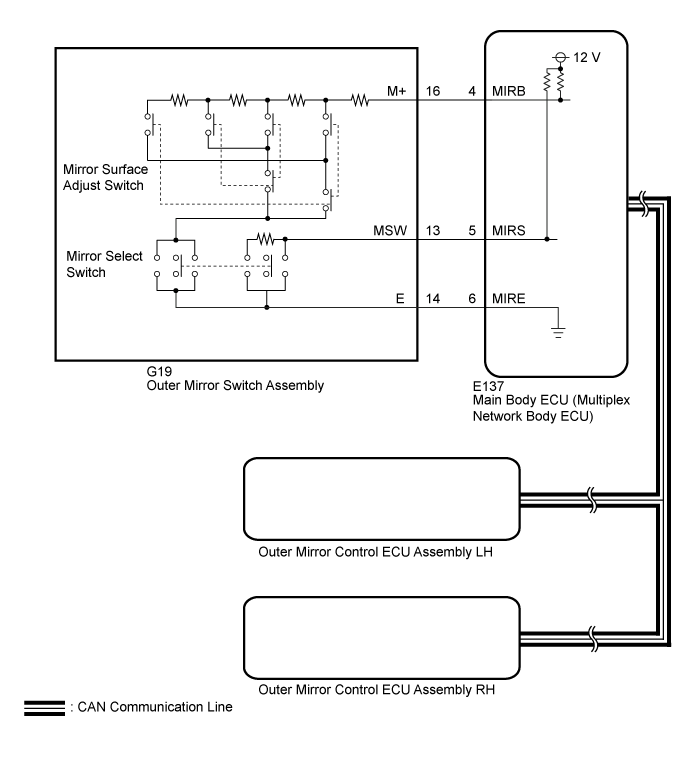
WIRING DIAGRAM
INSPECTION PROCEDURE
READ VALUE USING GTS (POWER MIRROR SWITCH)
INSPECT OUTER MIRROR SWITCH ASSEMBLY
CHECK HARNESS AND CONNECTOR (OUTER MIRROR SWITCH ASSEMBLY - MAIN BODY ECU [MULTIPLEX NETWORK BODY ECU])
POWER MIRROR CONTROL SYSTEM (w/ Retract Mirror) - Power Mirror cannot be Adjusted with Power Mirror Switch |
DESCRIPTION
When the outer mirror switch assembly mirror select switch is operated, right/left selection signals are sent to the main body ECU (multiplex network body ECU). The main body ECU (multiplex network body ECU) sends the received right/left selection signals to the outer mirror control ECU assemblies via CAN communication.
WIRING DIAGRAM
INSPECTION PROCEDURE
- NOTICE:
- First perform the communication function inspections in How to Proceed with Troubleshooting to confirm that there are no CAN communication malfunctions before troubleshooting this problem (Click here).
- If the main body ECU (multiplex network body ECU) is replaced, refer to the Entry and Start System (Click here).
| 1.READ VALUE USING GTS (POWER MIRROR SWITCH) |
Using the GTS, read the Data List. (Click here).
Main BodyTester Display
| Measurement Item/Range
| Normal Condition
| Diagnostic Note
|
Mirror Selection SW (R)
| Mirror select switch signal for RH mirror / ON or OFF
| ON: Mirror select switch is R position
OFF: Mirror select switch is except R position
| -
|
Mirror Selection SW (L)
| Mirror select switch signal for LH mirror / ON or OFF
| ON: Mirror select switch is L position
OFF: Mirror select switch is except L position
| -
|
Mirror Position SW (R)
| Mirror surface adjust switch signal (Right) / ON or OFF
| ON: Mirror surface adjust switch pressed right
OFF: Mirror surface adjust switch not pressed right
| -
|
Mirror Position SW (L)
| Mirror surface adjust switch signal (Left) / ON or OFF
| ON: Mirror surface adjust switch not pressed left
OFF: Mirror surface adjust switch pressed left
| -
|
Mirror Position SW (Up)
| Mirror surface adjust switch signal (Up) / ON or OFF
| ON: Mirror surface adjust switch pressed up
OFF: Mirror surface adjust switch not pressed up
| -
|
Mirror Position SW (Dwn)
| Mirror surface adjust switch signal (Down) / ON or OFF
| ON: Mirror surface adjust switch pressed down
OFF: Mirror surface adjust switch not pressed down
| -
|
- OK:
- On the GTS screen, each item changes between ON and OFF according to above chart.
Result
| Proceed to
|
OK
| A
|
NG (for LHD)
| B
|
NG (for RHD)
| C
|
| | REPLACE MAIN BODY ECU (MULTIPLEX NETWORK BODY ECU) (Click here) |
|
|
| | REPLACE MAIN BODY ECU (MULTIPLEX NETWORK BODY ECU) (Click here) |
|
|
| 2.INSPECT OUTER MIRROR SWITCH ASSEMBLY |
Remove the outer mirror switch assembly (Click here).
Inspect the outer mirror switch assembly (Click here).
| 3.CHECK HARNESS AND CONNECTOR (OUTER MIRROR SWITCH ASSEMBLY - MAIN BODY ECU [MULTIPLEX NETWORK BODY ECU]) |
Disconnect the G19 outer mirror switch assembly connector.
Disconnect the E137 main body ECU (multiplex network body ECU) connector.
Measure the resistance according to the value(s) in the table below.
- Standard Resistance:
Tester Connection
| Condition
| Specified Condition
|
G19-16 (M+) - E137-4 (MIRB)
| Always
| Below 1 Ω
|
G19-13 (MSW) - E137-5 (MIRS)
| Always
| Below 1 Ω
|
G19-14 (E) - E137-6 (MIRE)
| Always
| Below 1 Ω
|
G19-16 (M+) or E137-4 (MIRB) - Body ground
| Always
| 10 kΩ or higher
|
G19-13 (MSW) or E137-5 (MIRS) - Body ground
| Always
| 10 kΩ or higher
|
G19-14 (E) or E137-6 (MIRE) - Body ground
| Always
| 10 kΩ or higher
|
Result
| Proceed to
|
OK (for LHD)
| A
|
OK (for RHD)
| B
|
NG
| C
|
| | REPLACE MAIN BODY ECU (MULTIPLEX NETWORK BODY ECU) (Click here) |
|
|
| | REPAIR OR REPLACE HARNESS OR CONNECTOR |
|
|
| A |
|
|
|
| REPLACE MAIN BODY ECU (MULTIPLEX NETWORK BODY ECU) (Click here) |
|