INSTALL NO. 2 AIR OUTLET GRILLE ASSEMBLY (w/ Rear Air Conditioning System)
INSTALL NO. 1 AIR OUTLET GRILLE ASSEMBLY (w/ Rear Air Conditioning System)
Roof Headlining (W/ Sliding Roof) -- Reassembly |
- HINT:
- Use the same procedure for RHD and LHD vehicles.
- The procedure listed below is for LHD vehicles.
| 1. INSTALL ANTENNA CORD SUB-ASSEMBLY |
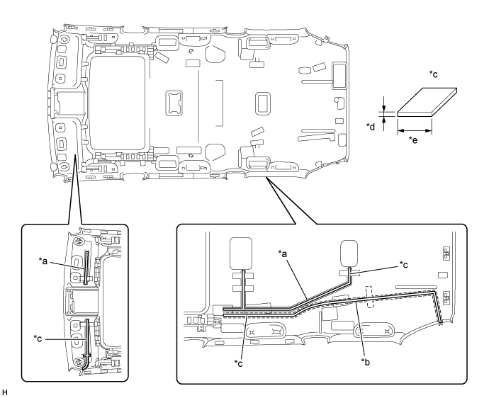
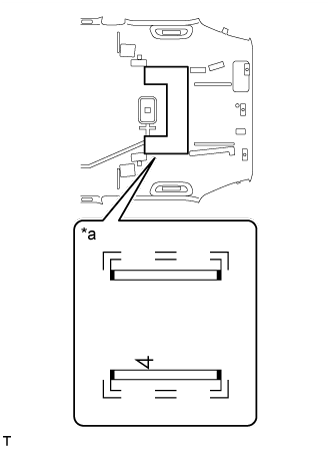
w/o Sliding Roof:
Apply new double-sided tape as shown in the illustration.
- HINT:
- Attach double-sided tape to the hatched areas shown in the illustration below.

Align the red tape wound around the antenna cord with the V markings on the roof headlining and the notch at the rear of the headlining, and attach the antenna cord to the double-sided tape.
Attach the 2 clamps and fit the antenna into the notch.
w/ Sliding Roof:
Apply new double-sided tape as shown in the illustration.
- HINT:
- Attach double-sided tape to the hatched areas shown in the illustration below.
Align the red tape wound around the antenna cord with the V markings on the roof headlining and the notch at the rear of the headlining, and attach the antenna cord to the double-sided tape.
Attach the 4 clamps and fit the antenna into the notch.

| 2. INSTALL NO. 1 ROOF WIRE |
Place double-sided tape along the center of the harness marking and washer marking.
- HINT:
- Make sure that the double-sided tape is not peeling off or misaligned.
Text in Illustration *a Harness Marking *b Washer Marking *c Double-sided Tape *d 1 mm (0.0394 in.) *e 10 mm (0.394 in.) - -
Remove the peeling paper from the double-sided tape while not touching the adhesive side.
Align the triangle mark of the roof wire protector with the V mark of the headlining as shown in the illustration, and then attach the roof wire protector.
Attach each clamp as shown in the illustration.
Align the roof wire and washer hose with the V marks of the headlining as shown in the illustration, and attach them to the headlining.
- HINT:
- Attach the washer hose from the front to the point labeled A, and attach the washer hose from the rear to the point labeled B as shown in the illustration.
- Attach the extra length of the washer hose to the part labeled C in the illustration.
Turn the visor connectors approximately 90° clockwise to install them to the roof headlining.
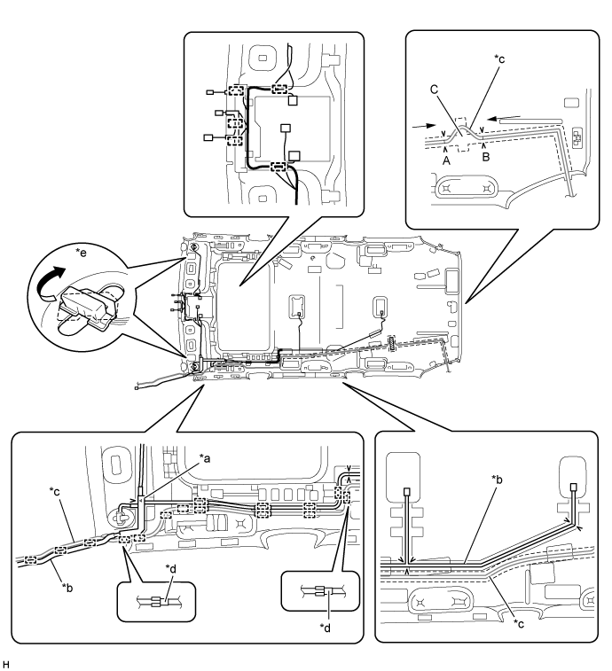
Text in Illustration *a Protector *b No. 1 Roof Wire *c Washer Hose *d Marking Tape *e Visor Connector - -
Place tape at the wire harness marking and washer marking locations as shown in the illustration to fix the roof wire and washer hose in place.
- HINT:
- Apply sufficient pressure when placing tape.
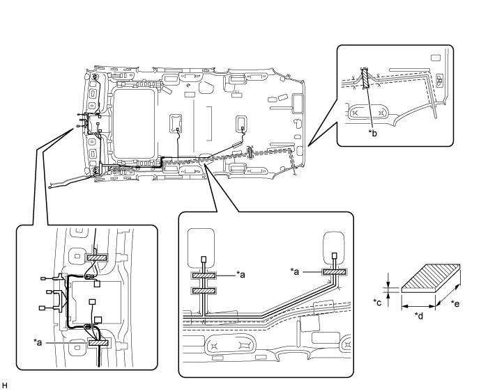
Text in Illustration *a Harness Marking *b Washer Marking *c 1 mm (0.0394 in.) *d 20 mm (0.787 in.) *e 100 mm (3.94 in.) - - 
Tape - -
| 3. INSTALL NO. 4 ROOF SILENCER PAD |
 |
Align the silencer marking on the roof headlining with the No. 4 roof silencer pad and install the No. 4 roof silencer pad using double-sided tape as shown in the illustration.
Text in Illustration *a Silencer Marking
| 4. INSTALL NO. 1 ROOF SILENCER PAD |
 |
Align the silencer marking on the roof headlining with the No. 1 roof silencer pad and install the No. 1 roof silencer pad using double-sided tape as shown in the illustration.
Text in Illustration *a Silencer Marking
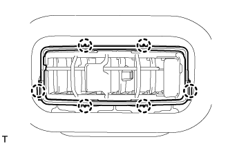
| 5. INSTALL NO. 2 AIR OUTLET GRILLE ASSEMBLY (w/ Rear Air Conditioning System) |
- HINT:
- Use the same procedure for both No. 2 air outlet grille assemblies.
Attach the 6 claws to install the No. 2 air outlet grille assembly.
 |
| 6. INSTALL NO. 1 AIR OUTLET GRILLE ASSEMBLY (w/ Rear Air Conditioning System) |
- HINT:
- Use the same procedures described for the No. 2 air outlet grille assembly.