Front Console Box (W/ Cool Box) -- Installation |
- HINT:
- Use the same procedures for LHD and RHD vehicles.
- The procedures listed below are for LHD vehicles.
- A bolt without a torque specification is shown in the standard bolt chart (Click here).
| 1. INSTALL COOLING BOX ASSEMBLY |
Attach the 2 claws.
Connect the connector.
Sufficiently apply compressor oil to 2 new O-rings.
- Compressor oil:
- ND-OIL 8 or equivalent
Install the 2 O-rings on the 2 cooler pipes.
Connect the 2 cooler pipes with the 2 bolts.
- Torque:
- 5.4 N*m{55 kgf*cm, 48 in.*lbf}
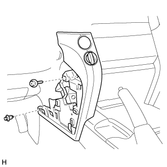
Install the cooling box assembly with the 4 bolts and 2 screws.
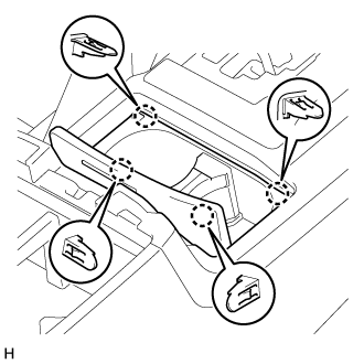
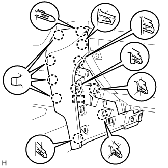
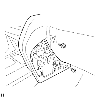
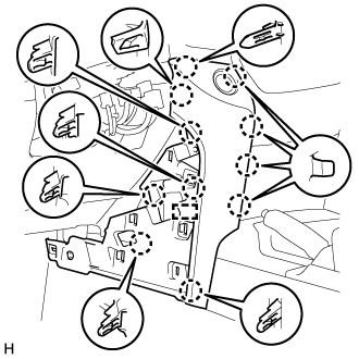
| 2. INSTALL REAR CONSOLE END PANEL SUB-ASSEMBLY |
 |
Connect the connectors and clamps.
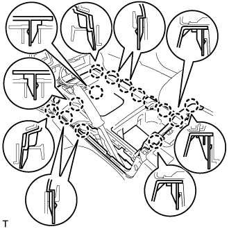
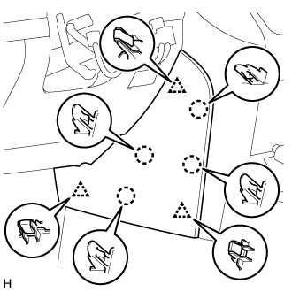
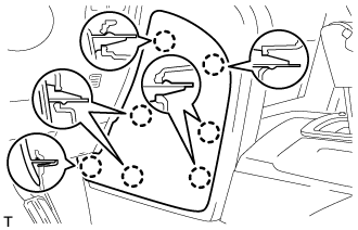
Attach the 7 claws to install the rear console end panel sub-assembly.
| 3. INSTALL NO. 1 COOLER COVER |
Attach the claw on the upper part of the cooler cover, and then attach the clamp on the lower part of the cooler cover to install it.
 |
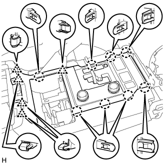
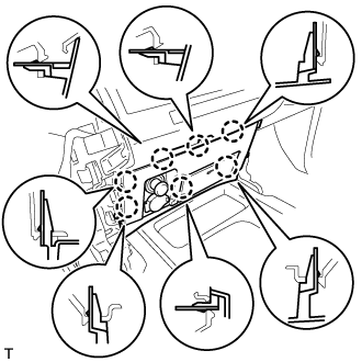
| 4. INSTALL UPPER CONSOLE PANEL SUB-ASSEMBLY |
for Type A:
Attach the 8 claws and 4 clips to install the upper console panel sub-assembly.
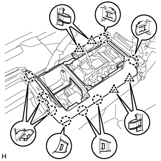
for Type B:
Connect the connectors.
Attach the 14 claws to install the console panel.
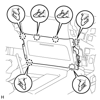
| 5. INSTALL REAR UPPER CONSOLE PANEL SUB-ASSEMBLY |
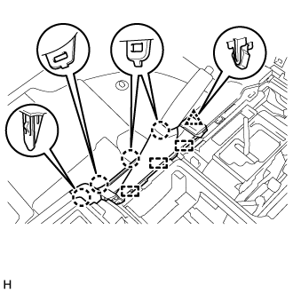 |
Attach the 4 claws, clip and 3 guides to install the rear upper console panel sub-assembly.
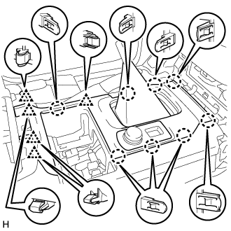
| 6. INSTALL UPPER CONSOLE PANEL |
for Automatic Transmission:
Connect the connectors.
Attach the 8 claws and 5 clips to install the upper console panel.
for Manual Transmission:
Connect the connectors.
Attach the 8 claws and 5 clips to install the upper console panel.
| 7. INSTALL CONSOLE CUP HOLDER BOX SUB-ASSEMBLY |
 |
Attach the 4 claws to install the console cup holder box sub-assembly.
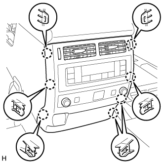
| 8. INSTALL LOWER CENTER INSTRUMENT CLUSTER FINISH PANEL SUB-ASSEMBLY |
for Type A:
Attach the 6 claws to install the lower center instrument cluster finish panel sub-assembly.
for Type B:
Connect the connectors.
Attach the 7 claws to install the lower center instrument cluster finish panel sub-assembly.
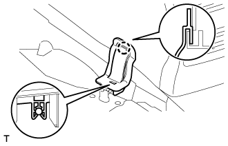
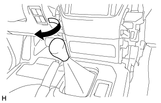
| 9. INSTALL SHIFT LEVER KNOB SUB-ASSEMBLY |
for Type A, for Automatic Transmission:
Install the shift lever knob sub-assembly and twist it in the direction indicated by the arrow.
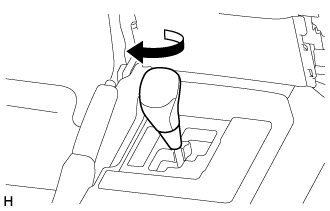
for Type A, for Manual Transmission:
Install the shift lever knob sub-assembly and twist it in the direction indicated by the arrow.
for Type B:
Install the shift lever knob sub-assembly and twist it in the direction indicated by the arrow.

Text in Illustration *A for Automatic Transmission *B for Manual Transmission
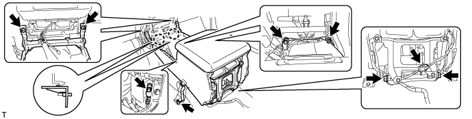
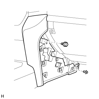
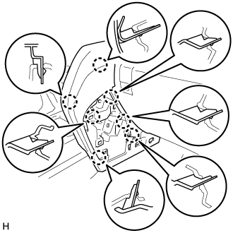
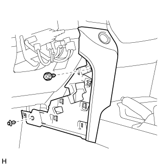
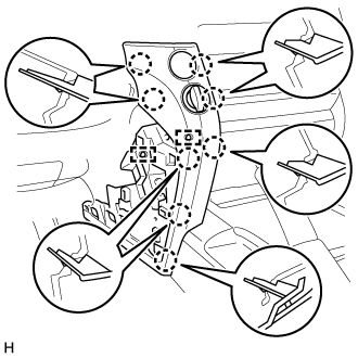
| 10. INSTALL LOWER INSTRUMENT PANEL PAD SUB-ASSEMBLY RH |
for Type A:
Attach the 11 claws and guide to install the lower instrument panel pad sub-assembly RH.
Install the screw and clip.
for Type B:
Attach the 7 claws to install the lower instrument panel pad sub-assembly RH.
Install the screw and clip.
| 11. INSTALL NO. 1 INSTRUMENT PANEL FINISH CUSHION |
for Type A:
Attach the 4 claws and 3 clips to install the No. 1 instrument panel finish panel cushion.

for Type B:
Attach the 7 claws to install the panel No. 1 instrument panel finish panel cushion.

| 12. INSTALL LOWER INSTRUMENT PANEL PAD SUB-ASSEMBLY LH |
for Type A:
Connect the connectors and clamps.
Attach the 11 claws and guide to install the lower instrument panel pad sub-assembly LH.
Install the screw and clip.
for Type B:
Connect the connectors and clamps.
Attach the 8 claws and 2 guides to install the lower instrument panel pad sub-assembly LH.
Install the screw and clip.
| 13. INSTALL NO. 2 INSTRUMENT PANEL FINISH PANEL CUSHION |
for Type A:
Attach the 4 claws and 3 clips to install the No. 2 instrument panel finish panel cushion.
for Type B:
Attach the 7 claws to install the No. 2 instrument panel finish panel cushion.
| 14. INSTALL FRONT SEAT ASSEMBLY LH (for Manual Seat) |
| 15. INSTALL FRONT SEAT ASSEMBLY LH (for Power Seat) |
| 16. CHARGE REFRIGERANT |
- SST
- 09985-20010(09985-02130,09985-02150,09985-02090,09985-02110,09985-02010,09985-02050,09985-02060,09985-02070)
Perform vacuum purging using a vacuum pump.
Charge refrigerant HFC-134a (R134a).
Standard: Condenser Core Thickness Air Conditioning Type Cool Box Refrigerant Charging Amount 22 mm (0.866 in.) w/o Rear Cooler w/ Cool Box 870 +/-50 g (30.7 +/-1.76 oz.) w/o Cool Box 870 +/-50 g (30.7 +/-1.76 oz.) w/ Rear Cooler w/ Cool Box 1010 +/-50 g (35.6 +/-1.76 oz.) w/o Cool Box 970 +/-50 g (34.2 +/-1.76 oz.) 16 mm (0.630 in.) w/o Rear Cooler w/ Cool Box 770 +/-50 g (27.2 +/-1.76 oz.) w/o Cool Box 770 +/-50 g (27.2 +/-1.76 oz.) w/ Rear Cooler w/ Cool Box 970 +/-50 g (34.2 +/-1.76 oz.) w/o Cool Box 920 +/-50 g (32.5 +/-1.76 oz.) 
- NOTICE:
- Do not operate the cooler compressor before charging refrigerant as the cooler compressor will not work properly without any refrigerant, and will overheat.
- Approximately 100g (3.53 oz.) of refrigerant may need to be charged after bubbles disappear. The refrigerant amount should be checked by measuring its quantity, and not with the sight glass.
| 17. WARM UP ENGINE |
Warm up the engine at less than 1850 rpm for 2 minutes or more after charging the refrigerant.
- NOTICE:
- Be sure to warm up the compressor when turning the A/C switch is on after removing and installing the cooler refrigerant lines (including the compressor), to prevent damage to the compressor.
| 18. CHECK FOR REFRIGERANT GAS LEAK |
After recharging the refrigerant gas, check for refrigerant gas leakage using a halogen leak detector.
Perform the operation under these conditions:
- Stop the engine.
- Secure good ventilation (the halogen leak detector may react to volatile gases other than refrigerant, such as evaporated gasoline or exhaust gas).
- Repeat the test 2 or 3 times.
- Make sure that some refrigerant remains in the refrigeration system. When compressor is off: approximately 392 to 588 kPa (4.0 to 6.0 kgf/cm2, 57 to 85 psi).
- Stop the engine.
Using a halogen leak detector, check the refrigerant line for leakage.
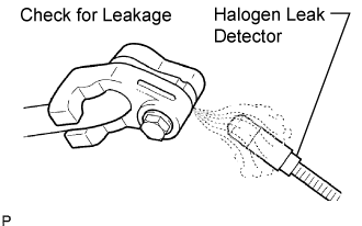 |
If a gas leak is not detected on the drain hose, remove the blower motor control (blower resistor) from the cooling unit. Insert the halogen leak detector sensor into the unit and perform the test.
Disconnect the connector and wait for approximately 20 minutes. Bring the halogen leak detector close to the pressure switch and perform the test.
| 19. INSTALL UPPER RADIATOR SUPPORT SEAL |
Install the upper radiator support seal with the 7 clips.