Front Console Box (W/ Cool Box) -- Removal |
- HINT:
- Use the same procedures for LHD and RHD vehicles.
- The procedures listed below are for LHD vehicles.
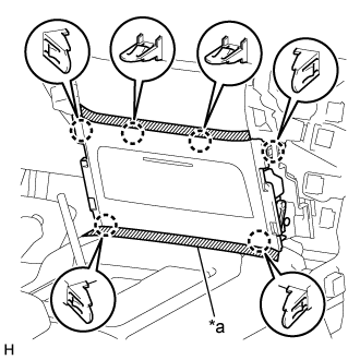
| 1. REMOVE UPPER RADIATOR SUPPORT SEAL |
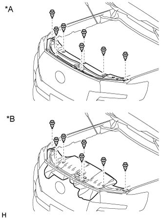
Remove the 7 clips and upper radiator support seal.
Text in Illustration *A for Gasoline *B for Diesel
 |
| 2. RECOVER REFRIGERANT FROM REFRIGERATION SYSTEM |
Start the engine.
Turn the A/C switch on.
Operate the cooler compressor while the engine speed is approximately 1000 rpm for 5 to 6 minutes to circulate the refrigerant and collect the compressor oil remaining in each component into the cooler compressor.
Stop the engine.
Recover the refrigerant from the A/C system using a refrigerant recovery unit.
| 3. REMOVE FRONT SEAT ASSEMBLY LH (for Power Seat) |
| 4. REMOVE FRONT SEAT ASSEMBLY LH (for Manual Seat) |
| 5. REMOVE NO. 2 INSTRUMENT PANEL FINISH PANEL CUSHION |
for Type A:
Put protective tape around the No. 2 instrument panel finish panel cushion.
Text in Illustration *a Protective Tape Using a moulding remover B, detach the 4 claws and 3 clips and remove the No. 2 instrument panel finish panel cushion.
for Type B:
Put protective tape around the No. 2 instrument panel finish panel cushion.
Text in Illustration *a Protective Tape Using a moulding remover, detach the 7 claws and remove the No. 2 instrument panel finish panel cushion.
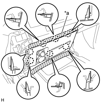
| 6. REMOVE LOWER INSTRUMENT PANEL PAD SUB-ASSEMBLY LH |
for Type A:
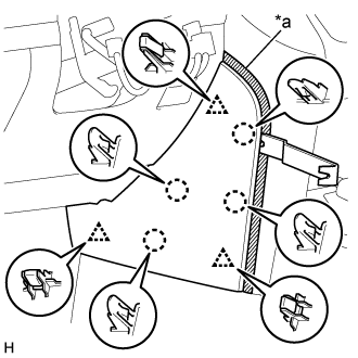
Put protective tape around the lower instrument panel pad sub-assembly LH.
Text in Illustration *a Protective Tape Remove the clip and screw.
Detach the 11 claws and guide.
Disconnect the connector and detach the clamps and remove the lower instrument panel pad sub-assembly LH.
for Type B:
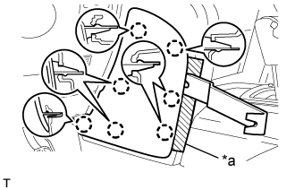
Put protective tape around the lower instrument panel pad sub-assembly LH.
Text in Illustration *a Protective Tape Remove the clip and screw.
Detach the 8 claws and 2 guides and remove the lower instrument panel pad sub-assembly LH.
| 7. REMOVE NO. 1 INSTRUMENT PANEL FINISH CUSHION |
for Type A:
Put protective tape around the No. 1 instrument panel finish panel cushion.
Text in Illustration *a Protective Tape Using a moulding remover B, detach the 4 claws and 3 clips and remove the No. 2 instrument panel finish panel cushion.
for Type B:
Put protective tape around the No. 1 instrument panel finish panel cushion.
Text in Illustration *a Protective Tape Using a moulding remover, detach the 7 claws and remove the No. 2 instrument panel finish panel cushion.
| 8. REMOVE LOWER INSTRUMENT PANEL PAD SUB-ASSEMBLY RH |
for Type A:
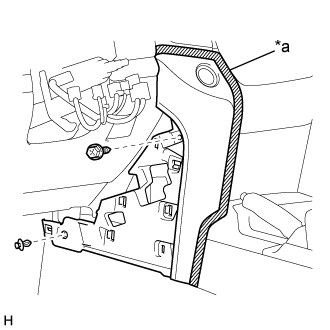
Put protective tape around the lower instrument panel pad sub-assembly RH.
Text in Illustration *a Protective Tape Remove the clip and screw.
Detach the 11 claws and guide and remove the lower instrument panel pad sub-assembly RH.
for Type B:
Put protective tape around the lower instrument panel pad sub-assembly RH.
Text in Illustration *a Protective Tape Remove the clip and screw.
Detach the 7 claws and remove the lower instrument panel pad sub-assembly RH.
| 9. REMOVE SHIFT LEVER KNOB SUB-ASSEMBLY |
for Type A, for Automatic Transmission:
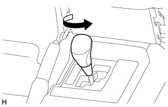
Twist the shift lever knob sub-assembly in the direction indicated by the arrow and remove it.
for Type A, for Manual Transmission:
Twist the shift lever knob sub-assembly in the direction indicated by the arrow and remove it.
for Type B:
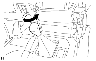
Twist the shift lever knob sub-assembly in the direction indicated by the arrow and remove it.
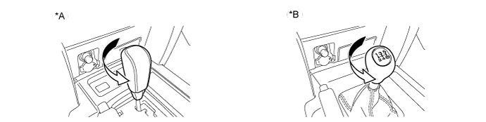
Text in Illustration *A for Automatic Transmission *B for Manual Transmission
| 10. REMOVE LOWER CENTER INSTRUMENT CLUSTER FINISH PANEL SUB-ASSEMBLY |
for Type A:
Put protective tape around the lower center instrument cluster finish panel sub-assembly.
Text in Illustration *a Protective Tape Detach the 6 claws and remove the lower center instrument cluster finish panel sub-assembly.
for Type B:
Put protective tape around the lower center instrument cluster finish panel sub-assembly.
Text in Illustration *a Protective Tape Detach the 7 claws.
Disconnect the connectors and remove the lower center instrument cluster finish panel sub-assembly.
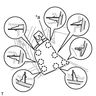
| 11. REMOVE CONSOLE CUP HOLDER BOX SUB-ASSEMBLY |
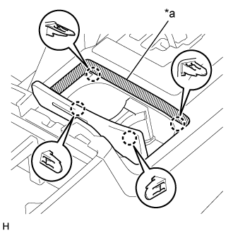 |
Put protective tape around the lower console cup holder box sub-assembly.
Text in Illustration *a Protective Tape
Detach the 4 claws and remove the console cup holder box sub-assembly.
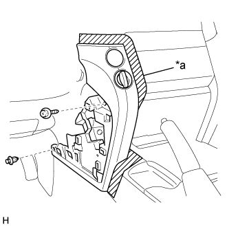
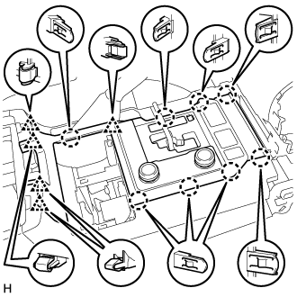
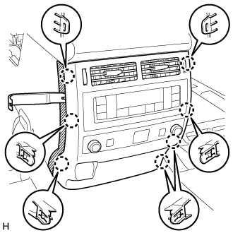
| 12. REMOVE UPPER CONSOLE PANEL |
for Automatic Transmission:
Put protective tape around the upper console panel.
Text in Illustration *a Protective Tape Detach the 8 claws and 5 clips.
Disconnect the connectors and remove the upper console panel.

for Manual Transmission:
Put protective tape around the upper console panel.
Text in Illustration *a Protective Tape Detach the 8 claws and 5 clips.
Disconnect the connectors and remove the upper console panel.
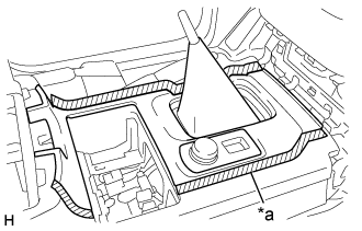
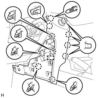
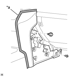
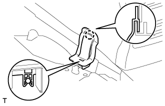
| 13. REMOVE REAR UPPER CONSOLE PANEL SUB-ASSEMBLY |
 |
Put protective tape around the upper rear console panel sub-assembly.
Text in Illustration *a Protective Tape
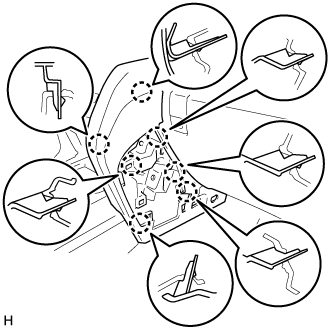
Detach the 4 claws, clip and 3 guides and remove the upper rear console panel sub-assembly.
 |
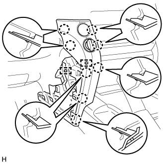
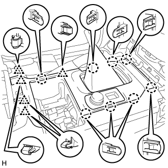
| 14. REMOVE UPPER CONSOLE PANEL SUB-ASSEMBLY |
for Type A:
Put protective tape around the upper console panel sub-assembly.
Text in Illustration *a Protective Tape Detach the 8 claws and 4 clips and remove the upper console panel sub-assembly.
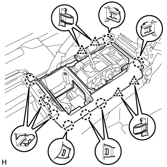
for Type B:
Put protective tape around the upper console panel sub-assembly.
Text in Illustration *a Protective Tape Detach the 14 claws.
Detach the 14 claws. (b) Disconnect the connectors and remove the upper console panel sub-assembly.
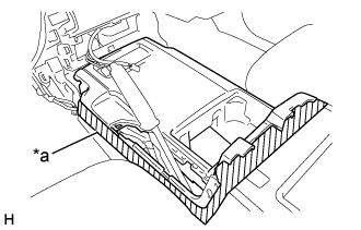
| 15. REMOVE NO. 1 COOLER COVER |
Detach the clamp on the lower part of the cooler cover, and then pull the cooler cover upward to remove it.
 |
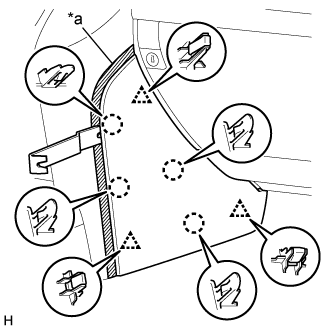
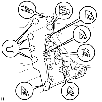
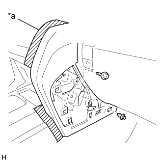
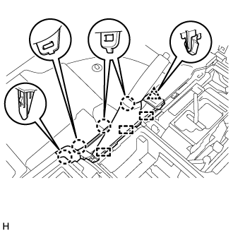
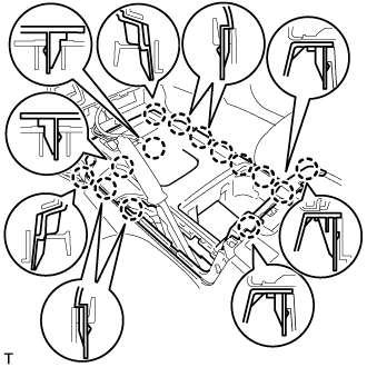
| 16. REMOVE REAR CONSOLE END PANEL SUB-ASSEMBLY |
 |
Put protective tape around the rear console end panel sub-assembly.
Text in Illustration *a Protective Tape
Using a moulding remover B, detach the 7 claws.
Disconnect the connectors and detach the clamps and remove the rear console end panel sub-assembly.
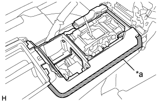
| 17. REMOVE COOLING BOX ASSEMBLY |
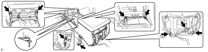
Remove the 4 bolts and 2 screws.
Remove the 2 bolts and disconnect the 2 cooler pipes.
Remove the 2 O-rings from the 2 cooler pipes.
Disconnect the connector.
Detach the 2 claws and remove the cooling box assembly.