DISABLE AUTOAWAY/RETURN FUNCTION (for Power Tilt and Power Telescopic Steering Column)
REMOVE NO. 1 INSTRUMENT PANEL UNDER COVER SUB-ASSEMBLY (w/ Floor Under Cover)
REMOVE LOWER NO. 1 INSTRUMENT PANEL AIRBAG ASSEMBLY (w/ Driver Side Knee Airbag)
REMOVE LOWER INSTRUMENT PANEL SUB-ASSEMBLY (w/o Driver Side Knee Airbag)
REMOVE NO. 2 INSTRUMENT PANEL UNDER COVER SUB-ASSEMBLY (w/ Floor Under Cover)
REMOVE LOWER NO. 2 INSTRUMENT PANEL AIRBAG ASSEMBLY (w/ Passenger Side Knee Airbag)
REMOVE LOWER INSTRUMENT PANEL (w/o Passenger Side Knee Airbag)
REMOVE NO. 1 CENTER INSTRUMENT CLUSTER FINISH PANEL (w/o Navigation System)
REMOVE RADIO AND DISPLAY RECEIVER ASSEMBLY (for Radio and Display Type)
REMOVE MULTI-MEDIA MODULE RECEIVER ASSEMBLY (w/ Navigation System)
REMOVE AIR CONDITIONING CONTROL ASSEMBLY (w/o Navigation System)
REMOVE FRONT NO. 4 SPEAKER ASSEMBLY (w/ Front Center Speaker)
Instrument Panel Safety Pad -- Removal |
- HINT:
- Use the same procedure for RHD and LHD vehicles.
- The procedure listed below is for LHD vehicles.
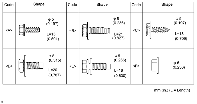
| 1. TABLE OF BOLT, SCREW AND NUT |
- HINT:
- All bolts, screws and nuts relevant to installing and removing the instrument panel are shown along with their alphabet code in the table below.
| 2. RECOVER REFRIGERANT FROM REFRIGERATION SYSTEM (w/ Cool Box) |
Start the engine.
Turn the A/C switch on.
Operate the cooler compressor while the engine speed is approximately 1000 rpm for 5 to 6 minutes to circulate the refrigerant and collect the compressor oil remaining in each component into the cooler compressor.
Stop the engine.
Recover the refrigerant from the A/C system using a refrigerant recovery unit.
| 3. DISABLE AUTOAWAY/RETURN FUNCTION (for Power Tilt and Power Telescopic Steering Column) |
Disable the autoaway/return function by changing the customize parameter (Click here).
- CAUTION:
- Record the current customize parameter setting (whether the autoaway/return function is enabled or disabled) in order to restore the current setting after finishing the operation.
- HINT:
- Performing the above operation causes the autoaway/return function to be disabled when the engine switch is turned off.
Turn the ignition switch on (IG). Operate the tilt and telescopic switch to fully extend and lower the steering column assembly.
Turn the ignition switch off.
| 4. PRECAUTION |
- NOTICE:
- After turning the ignition switch off, waiting time may be required before disconnecting the cable from the battery terminal. Therefore, make sure to read the disconnecting the cable from the battery terminal notice before proceeding with work (Click here).
| 5. DISCONNECT CABLE FROM NEGATIVE BATTERY TERMINAL |
- NOTICE:
- When disconnecting the cable, some systems need to be initialized after the cable is reconnected (Click here).
| 6. REMOVE FRONT SEAT ASSEMBLY LH |
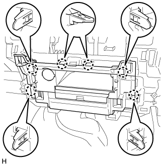
for Manual Seat:
(Click here)
for Power Seat:
(Click here)
| 7. REMOVE FRONT SEAT ASSEMBLY RH |
for Manual Seat:
(Click here)
for Power Seat:
(Click here)
for Bench Seat Type:
(Click here)
| 8. REMOVE HEADLIGHT DIMMER SWITCH ASSEMBLY |
| 9. REMOVE REAR CONSOLE BOX SUB-ASSEMBLY (w/o Cool Box) |
| 10. REMOVE COOLING BOX ASSEMBLY (w/ Cool Box) |
| 11. REMOVE LOWER CONSOLE BOX (w/o Console Box Lid) |
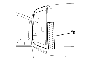
| 12. REMOVE INSTRUMENT SIDE PANEL LH |
 |
Put protective tape around the instrument side panel LH.
Text in Illustration *a Protective Tape
Using a moulding remover A, detach the 6 claws and remove the instrument side panel LH.
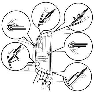
| 13. REMOVE NO. 1 INSTRUMENT CLUSTER FINISH PANEL GARNISH |
 |
Put protective tape around the No. 1 instrument cluster finish panel garnish.
Text in Illustration *a Protective Tape
Using a moulding remover A, detach the 3 claws and remove the No. 1 instrument cluster finish panel garnish.
| 14. REMOVE NO. 2 INSTRUMENT CLUSTER FINISH PANEL GARNISH |
 |
Put protective tape around the No. 2 instrument cluster finish panel garnish.
Text in Illustration *a Protective Tape
Using a moulding remover A, detach the 2 claws and remove the No. 2 instrument cluster finish panel garnish.
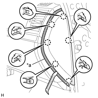
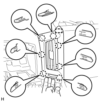
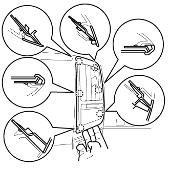
| 15. REMOVE NO. 2 INSTRUMENT CLUSTER FINISH PANEL SUB-ASSEMBLY |
 |
Put protective tape around the No. 2 instrument cluster finish panel sub-assembly.
Text in Illustration *a Protective Tape
Detach the 9 claws.
Disconnect the connectors and remove the No. 2 instrument cluster finish panel sub-assembly.
| 16. REMOVE COMBINATION METER ASSEMBLY |
 |
Remove the 4 screws.
Disconnect the connectors and remove the combination meter assembly.
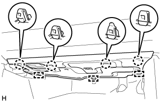
| 17. REMOVE FRONT DOOR SCUFF PLATE LH |
 |
Detach the 7 claws and 4 clips, and remove the front door scuff plate LH.
| 18. REMOVE NO. 1 INSTRUMENT PANEL UNDER COVER SUB-ASSEMBLY (w/ Floor Under Cover) |
 |
Remove the 2 screws <A>.
Text in Illustration *a Screw <A>
Detach the 3 claws.
Disconnect the connector and remove the No. 1 instrument panel under cover sub-assembly.
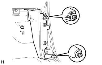
| 19. REMOVE COWL SIDE TRIM BOARD LH |
 |
Remove the cap nut.
Text in Illustration *a Cap Nut
Detach the 2 clips and remove the cowl side trim board LH.
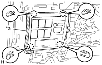
| 20. REMOVE LOWER NO. 1 INSTRUMENT PANEL FINISH PANEL |
 |
Using a screwdriver, detach the 2 claws and open the hole cover.
- HINT:
- Tape the screwdriver tip before use.
Text in Illustration *a Protective Tape
Put protective tape around the lower No. 1 instrument panel finish panel.
 |
Remove the 2 bolts <B>.
Text in Illustration *a Protective Tape *b Bolt <B>
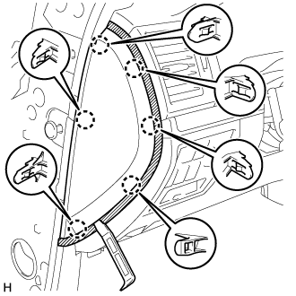
w/ Driver Side Knee Airbag:
Detach the 16 claws.
w/o Driver Side Knee Airbag:
Detach the 9 claws.
for Automatic Air Conditioning System:
Detach the 2 claws and remove the room temperature sensor.

Detach the 2 claws and disconnect the 2 control cables.
 |
Disconnect the connectors and remove the lower No. 1 instrument panel finish panel.
| 21. REMOVE NO. 1 SWITCH HOLE BASE |
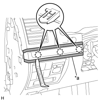
 |
Put protective tape around the No. 1 switch hole base.
Text in Illustration *a Protective Tape
Detach the 4 claws.
Disconnect the connectors and remove the No. 1 switch hole base.
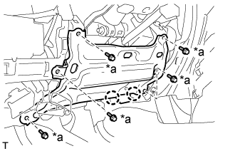
| 22. REMOVE LOWER NO. 1 INSTRUMENT PANEL AIRBAG ASSEMBLY (w/ Driver Side Knee Airbag) |
Remove the 5 bolts and driver side knee airbag assembly.
 |
Using a screwdriver, release the connector lock and disconnect the airbag connector.
Text in Illustration *a Connector Lock 
Protective Tape - NOTICE:
- When handling the airbag connector, take care not to damage the airbag wire harness.
| 23. REMOVE LOWER INSTRUMENT PANEL SUB-ASSEMBLY (w/o Driver Side Knee Airbag) |
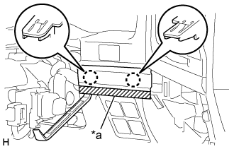
 |
Detach the 2 claws and disconnect the DLC3.
Remove the 5 bolts <B> and lower instrument panel sub-assembly.
Text in Illustration *a Bolt <B>
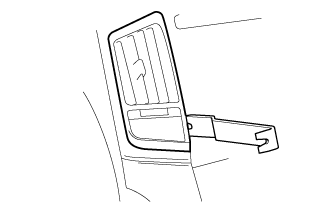
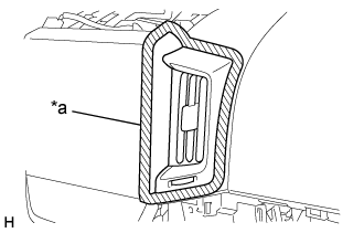
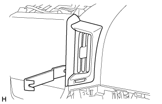
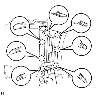
| 24. REMOVE NO. 1 INSTRUMENT PANEL REGISTER ASSEMBLY |
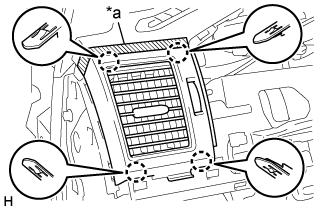 |
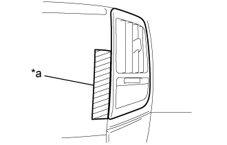
Put protective tape around the No. 1 instrument panel register assembly.
Text in Illustration *a Protective Tape
Detach the 4 claws and remove the No. 1 instrument panel register assembly.
| 25. REMOVE INSTRUMENT SIDE PANEL RH |
 |
Put protective tape around the instrument side panel RH.
Text in Illustration *a Protective Tape
Using a moulding remover A, detach the 6 claws and remove the instrument side panel RH.
w/ Airbag Cut Off Switch:
Disconnect the connector and remove the instrument side panel RH.
| 26. REMOVE FRONT DOOR SCUFF PLATE RH |
- HINT:
- Use the same procedures described for the LH side.
| 27. REMOVE NO. 2 INSTRUMENT PANEL UNDER COVER SUB-ASSEMBLY (w/ Floor Under Cover) |
 |
Detach the 4 claws and 3 guides.
Disconnect the connector and remove the No. 2 instrument panel under cover sub-assembly.
| 28. REMOVE COWL SIDE TRIM BOARD RH |
 |
Remove the cap nut.
Text in Illustration *a Cap Nut
Detach the 2 clips and remove the cowl side trim board LH.
| 29. REMOVE LOWER NO. 2 INSTRUMENT PANEL AIRBAG ASSEMBLY (w/ Passenger Side Knee Airbag) |
Remove the 4 bolts.
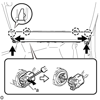 |
Detach the 4 claws and remove the front passenger side knee airbag assembly.
Using a screwdriver, release the connector lock and disconnect the airbag connector.
Text in Illustration *a Connector Lock Protective Tape - NOTICE:
- When handling the airbag connector, take care not to damage the airbag wire harness.
- CAUTION:
- Tape the screwdriver tip before use.
| 30. REMOVE LOWER INSTRUMENT PANEL (w/o Passenger Side Knee Airbag) |
 |
Remove the 2 bolts <B>.
Text in Illustration *a Bolt <B>
Detach the 4 claws and remove the lower instrument panel.
| 31. REMOVE NO. 3 INSTRUMENT CLUSTER FINISH PANEL GARNISH |
 |
Put protective tape around the No. 3 instrument cluster finish panel garnish.
Text in Illustration *a Protective Tape
Using a moulding remover A, detach the 6 claws and remove the No. 3 instrument cluster finish panel garnish.
| 32. REMOVE INSTRUMENT PANEL BOX DOOR KNOB |
- HINT:
- Use the same procedure for both instrument panel box door knobs.
Using a moulding remover B, detach the 2 claws and remove the instrument panel box door knob.
 |
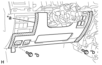
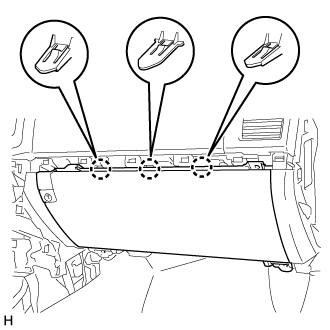
| 33. REMOVE LOWER NO. 2 INSTRUMENT PANEL FINISH PANEL |
 |
Put protective tape around the lower No. 2 instrument panel finish panel.
Remove the 4 screws <C>.
Text in Illustration *a Protective Tape *b Screw <C>
Detach the 3 claws.
 |
Disconnect the connector and remove the lower No. 2 instrument panel finish panel.
| 34. REMOVE NO. 2 INSTRUMENT PANEL REGISTER ASSEMBLY |
 |
Put protective tape around the No. 2 instrument panel register assembly.
Text in Illustration *a Protective Tape
Detach the 4 claws and remove the No. 2 instrument panel register assembly.
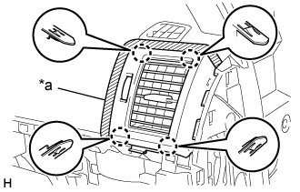
| 35. REMOVE NO. 3 INSTRUMENT PANEL REGISTER ASSEMBLY |
for Type A:
Put protective tape around the No. 3 instrument panel register assembly.
Text in Illustration *a Protective Tape Using moulding remover B, raise the No. 3 instrument panel register assembly.
Pull the No. 3 instrument panel register assembly by hand to detach the 7 claws and guide and remove the No. 3 instrument panel register assembly.
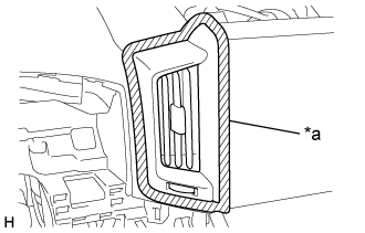
for Type B:
Put protective tape around the No. 3 instrument panel register assembly.
Text in Illustration *a Protective Tape Using moulding remover B, raise the No. 3 instrument panel register assembly.
Pull the No. 3 instrument panel register assembly by hand to detach the 6 claws and remove the No. 3 instrument panel register assembly.
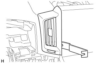
| 36. REMOVE NO. 4 INSTRUMENT PANEL REGISTER ASSEMBLY |
for Type A:
Put protective tape around the No. 3 instrument panel register assembly.
Text in Illustration *a Protective Tape Using moulding remover B, raise the No. 3 instrument panel register assembly.
Pull the No. 3 instrument panel register assembly by hand to detach the 7 claws and guide and remove the No. 3 instrument panel register assembly.
for Type B:
Put protective tape around the No. 3 instrument panel register assembly.
Text in Illustration *a Protective Tape Using moulding remover B, raise the No. 3 instrument panel register assembly.
Pull the No. 3 instrument panel register assembly by hand to detach the 6 claws and remove the No. 3 instrument panel register assembly.
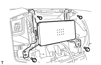
| 37. REMOVE MULTI-DISPLAY ASSEMBLY (w/ Navigation System) |
Remove the 2 screws and 2 bolts.
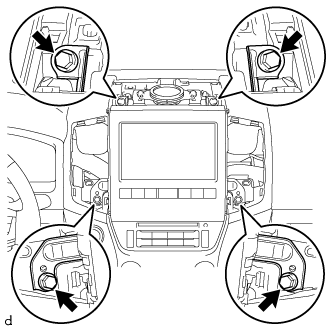 |
Pull the multi-display assembly to detach the 3 clips and 4 claws on the backside of the multi-display assembly.
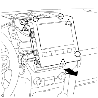 |
Disconnect the connectors and remove the multi-display assembly.
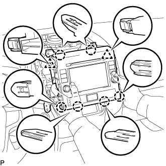
| 38. REMOVE NO. 1 CENTER INSTRUMENT CLUSTER FINISH PANEL (w/o Navigation System) |
for Type A:
Detach the 8 claws and 3 clips.
Disconnect the connectors and remove the No. 1 center instrument cluster finish panel.
for Type B:
Detach the 10 claws.
Disconnect the connectors and remove the No. 1 center instrument cluster finish panel.
| 39. REMOVE RADIO TUNER OPENING COVER (w/o Radio Receiver) |
 |
Remove the 2 bolts.
Remove the 2 screws and radio tuner opening cover.
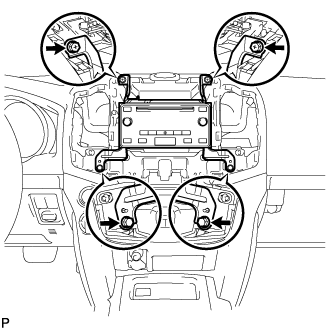
| 40. REMOVE RADIO AND DISPLAY RECEIVER ASSEMBLY (for Radio and Display Type) |
Remove the 2 screws and 2 bolts.
 |
Pull the radio and display receiver assembly with bracket to detach the 6 claws and 2 clips on the backside of the radio and display receiver assembly with bracket.
 |
Disconnect the connectors and remove the radio and display receiver assembly with bracket.
| 41. REMOVE RADIO RECEIVER ASSEMBLY (for Radio Receiver Type) |
w/o Entry and Start System:
Remove the 2 screws and 2 bolts.
Disconnect the connectors and remove the radio receiver.
w/ Entry and Start System:
Remove the 2 screws and 2 bolts.
Disconnect the connectors and remove the radio receiver.
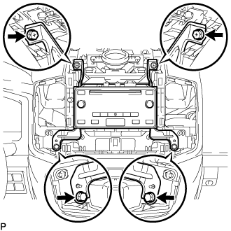
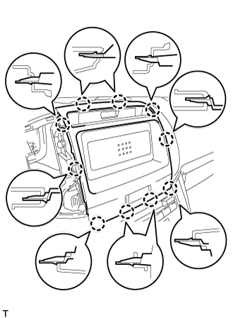
| 42. REMOVE MULTI-MEDIA MODULE RECEIVER ASSEMBLY (w/ Navigation System) |
Remove the 2 screws and 2 bolts.
 |
Pull the multi-media module receiver assembly to detach the 5 claws on the backside of the multi-media module receiver assembly.
 |
Disconnect the connectors and remove the multi-media module receiver assembly.
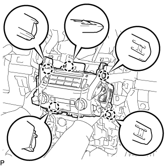
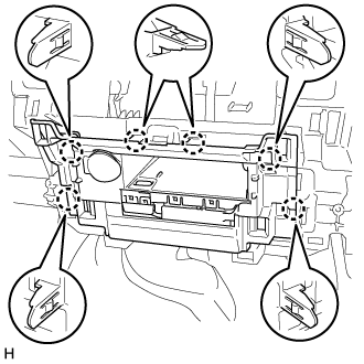
| 43. REMOVE AIR CONDITIONING CONTROL ASSEMBLY (w/o Navigation System) |
Pull the air conditioning control assembly to detach the 5 claws on the backside of the air conditioning control assembly.
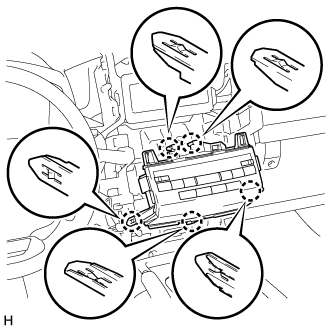 |
Disconnect the connectors and remove the air conditioning control assembly.
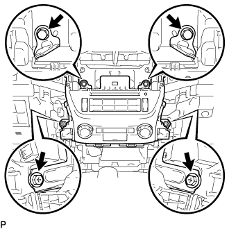
| 44. REMOVE ASSIST GRIP SUB-ASSEMBLY |
- HINT:
- Use the same procedure for both assist grip sub-assemblies.
Detach the 4 claws and remove the 2 assist grip plugs.
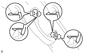 |
Remove the 2 bolts.
 |
Detach the 2 claws and remove the assist grip sub-assembly.
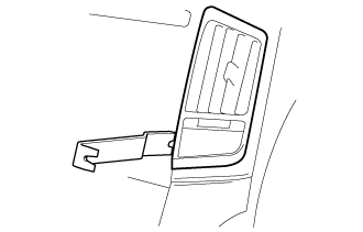
| 45. REMOVE FRONT PILLAR GARNISH LH |
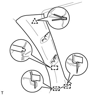 |
Detach the clip 3 guides, and remove the front pillar garnish LH.
w/ Speaker:
Disconnect the speaker connector and then remove the front pillar garnish.
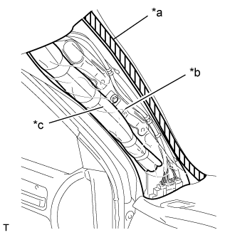
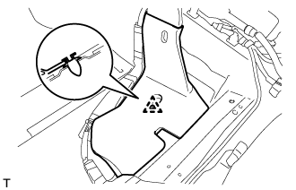
Protect the curtain shield airbag.
Thoroughly cover the airbag with a cloth or nylon sheet and fix the ends of the cover with adhesive tape, as shown in the illustration.
- NOTICE:
- Cover the curtain shield airbag with a protective cover as soon as the front pillar garnish is removed.
Text in Illustration *a Adhesive Tape *b Protective Cover *c Curtain Shield Airbag Assembly LH
 |
| 46. REMOVE FRONT PILLAR GARNISH RH |
- HINT:
- Use the same procedures described for the LH side.
| 47. REMOVE NO. 1 SPEAKER OPENING COVER ASSEMBLY |
 |
Put protective tape around the No. 1 speaker opening cover assembly.
Text in Illustration *a Protective Tape
Using a moulding remover A, detach the 8 clips and remove the No. 1 speaker opening cover assembly.
| 48. REMOVE NO. 1 INSTRUMENT PANEL SPEAKER PANEL SUB-ASSEMBLY |
 |
Put protective tape around the No. 1 instrument panel speaker panel sub-assembly.
Text in Illustration *a Protective Tape
Using a moulding remover A, detach the 3 claws and 2 guides and remove the No. 1 instrument panel speaker panel sub-assembly.
| 49. REMOVE NO. 2 INSTRUMENT PANEL SPEAKER PANEL SUB-ASSEMBLY |
 |
Put protective tape around the No. 2 instrument panel speaker panel sub-assembly.
Text in Illustration *a Protective Tape
Using a moulding remover A, detach the 3 claws and 2 guides and remove the No. 2 instrument panel speaker panel sub-assembly.
| 50. REMOVE FRONT NO. 4 SPEAKER ASSEMBLY (w/ Front Center Speaker) |
Remove the 2 bolts.
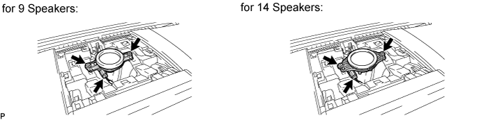
Remove the speaker and then disconnect the speaker connector.
- NOTICE:
- Do not touch the cone part of the speaker.
| 51. REMOVE FRONT NO. 2 SPEAKER ASSEMBLY |
- HINT:
- Use the same procedure for the RH and LH sides (Click here).
| 52. REMOVE CENTER INSTRUMENT CLUSTER FINISH PANEL SUB-ASSEMBLY |
w/o Wireless Charger:
Detach the 6 claws.
Disconnect the connectors and remove the center instrument cluster finish panel sub-assembly.
w/ Wireless Charger:
Detach the 6 claws.
Disconnect the connectors and remove the center instrument cluster finish panel sub-assembly.
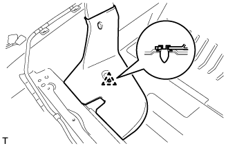
| 53. REMOVE REAR NO. 4 AIR DUCT (w/ Rear Air Duct) |
 |
Fold back the front floor carpet.
Detach the clip and remove the rear No. 4 air duct.
| 54. REMOVE REAR NO. 2 AIR DUCT (w/ Rear Air Duct) |
 |
Fold back the front floor carpet.
Detach the clip and remove the rear No. 2 air duct.
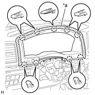
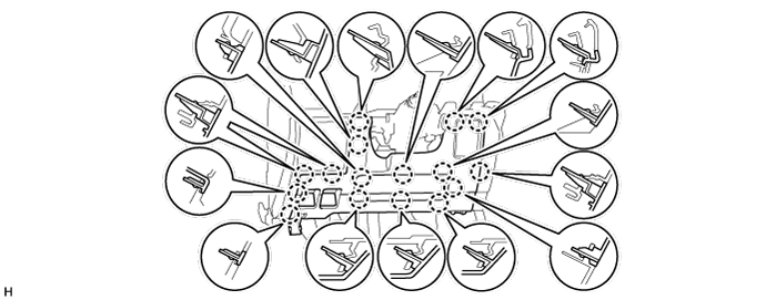
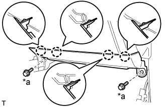
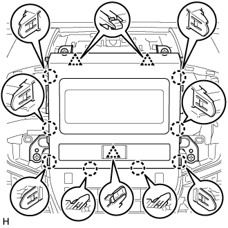
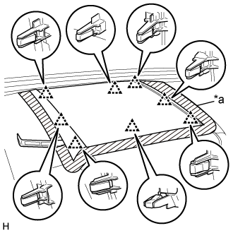
| 55. REMOVE INSTRUMENT PANEL SAFETY PAD ASSEMBLY |
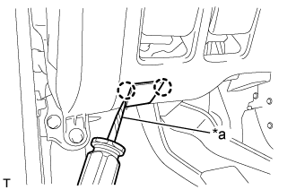
Disconnect the connector and detach the clamps.
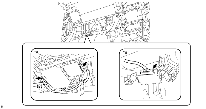
Text in Illustration *A w/ Multi-terrian Monitor System *B w/ TOYOTA Parking Assist-sensor System
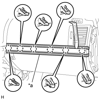
Disconnect the connectors and detach the clamps.
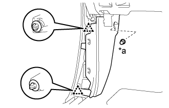
Remove the bolt and disconnect the wire harness.
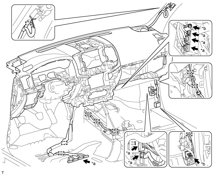
Text in Illustration *a Connector *b Bolt
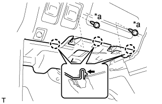
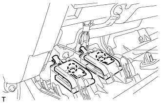
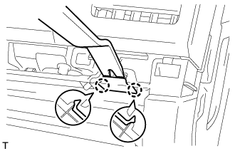
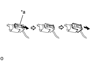
Pull and slide the lock slider in the direction indicated by the arrow to release the connector lock and disconnect the passenger airbag connector.
- NOTICE:
- When handling the passenger airbag connector, take care not to damage the airbag wire harness.
Text in Illustration *a Lock Slider
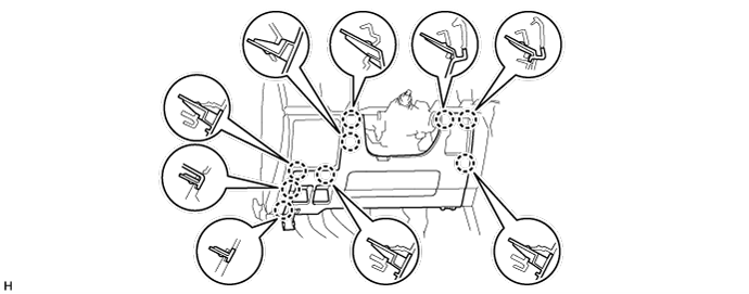
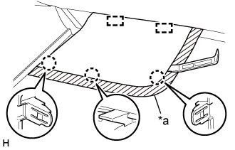
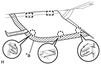
 |
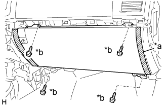
Disconnect the connectors.
Remove the 2 passenger airbag installation bolts <D>.
Remove the 6 bolts <E>.
Remove the 2 nuts <F>.
Remove the 2 bolts <B> and instrument panel safety pad assembly.
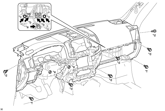
Text in Illustration *a Passenger Airbag Connector *b Connector *c Passenger Airbag Installation Bolt <D> *d Bolt <E> *e Nut <F> *f Bolt <B>