Air Conditioning System (For Automatic Air Conditioning System) Viscous Heater With Magnet Clutch Circuit
DESCRIPTION
WIRING DIAGRAM
INSPECTION PROCEDURE
READ VALUE USING GTS (IDLE UP/PWR HEATER SWITCH)
PERFORM ACTIVE TEST USING GTS (VISCOUS HEATER)
CHECK HARNESS AND CONNECTOR (IDLE UP SWITCH - BATTERY AND BODY GROUND)
INSPECT IDLE UP SWITCH
CHECK HARNESS AND CONNECTOR (IDLE UP SWITCH - AIR CONDITIONING AMPLIFIER ASSEMBLY)
INSPECT VISCOUS HEATER RELAY (VICS HTR RELAY)
CHECK HARNESS AND CONNECTOR (AIR CONDITIONING AMPLIFIER ASSEMBLY - BATTERY)
CHECK HARNESS AND CONNECTOR (VISCOUS HEATER RELAY - VISCOUS WITH MAGNET CLUTCH HEATER ASSEMBLY AND BATTERY)
CHECK VISCOUS WITH MAGNET CLUTCH HEATER ASSEMBLY
AIR CONDITIONING SYSTEM (for Automatic Air Conditioning System) - Viscous Heater with Magnet Clutch Circuit |
DESCRIPTION
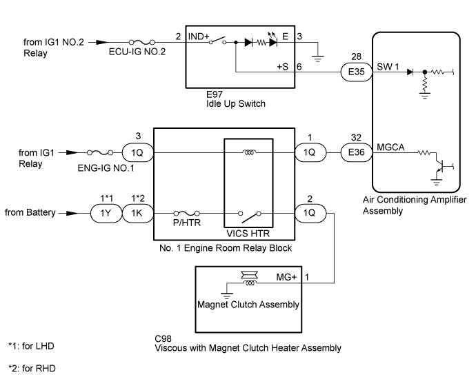
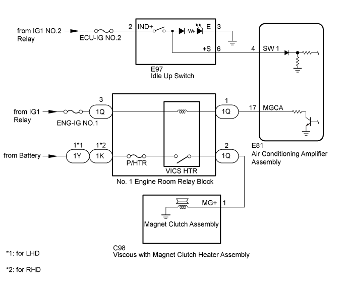
When the idle up switch is pushed, the air conditioning amplifier assembly turns on the viscous heater relay and operates the viscous heater. If the viscous heater does not operate when the idle up switch is pushed, there may be a problem in the circuit shown below.
WIRING DIAGRAM
INSPECTION PROCEDURE
| 1.READ VALUE USING GTS (IDLE UP/PWR HEATER SWITCH) |
Use the Data List to check if the idle up switch is functioning properly (Click here).
Air Conditioner Tester Display
| Measurement Item/Range
| Normal Condition
| Diagnostic Note
|
IDLE UP/PWR HEAT Switch
| Idle up switch / ON or OFF
| ON: Idle up switch on
OFF: Idle up switch off
| -
|
- OK:
- The display is as specified in the normal condition column.
| 2.PERFORM ACTIVE TEST USING GTS (VISCOUS HEATER) |
Select the Active Test, use the GTS to generate a control command, and then check that the viscous heater relay (VICS HTR) (Click here).
Tester Display
| Test Part
| Control Range
| Diagnostic Note
|
Viscous Heater
| Viscous heater relay
| ON / OFF
| -
|
- OK:
- Viscous heater relay operates using GTS.
| OK |
|
|
|
| REPLACE AIR CONDITIONING AMPLIFIER ASSEMBLY (Click here) |
|
| 3.CHECK HARNESS AND CONNECTOR (IDLE UP SWITCH - BATTERY AND BODY GROUND) |
Disconnect the idle up switch assembly connector.
Measure the resistance according to the value(s) in the table below.
- Standard Resistance:
Tester Connection
| Condition
| Specified Condition
|
E97-3 (E) - Body ground
| Always
| Below 1 Ω
|
Measure the voltage according to the value(s) in the table below.
- Standard Voltage:
Tester Connection
| Switch Condition
| Specified Condition
|
E97-2 (IND+) - Body ground
| Ignition switch off
| Below 1 V
|
E97-2 (IND+) - Body ground
| Ignition switch ON
| 11 to 14 V
|
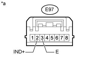
Text in Illustration*a
| Front view of wire harness connector
(to Idle Up Switch)
|
| | REPAIR OR REPLACE HARNESS OR CONNECTOR |
|
|
Remove the idle up switch (Click here).
Inspect the idle up switch (Click here ).
| 5.CHECK HARNESS AND CONNECTOR (IDLE UP SWITCH - AIR CONDITIONING AMPLIFIER ASSEMBLY) |
w/ Rear Heater:
Disconnect the E35 air conditioning amplifier assembly connector.
Disconnect the E97 idle up switch connector.
Measure the resistance according to the value(s) in the table below.
- Standard Resistance:
Tester Connection
| Condition
| Specified Condition
|
E35-28 (SW 1) - E97-6 (+S)
| Always
| Below 1 Ω
|
E35-28 (SW 1) or E97-6 (+S) - Body ground
| Always
| 10 kΩ or higher
|
w/o Rear Heater:
Disconnect the E81 air conditioning amplifier assembly connector.
Disconnect the E97 idle up switch connector.
Measure the resistance according to the value(s) in the table below.
- Standard Resistance:
Tester Connection
| Condition
| Specified Condition
|
E81-4 (SW 1) - E97-6 (+S)
| Always
| Below 1 Ω
|
E81-4 (SW 1) or E97-6 (+S) - Body ground
| Always
| 10 kΩ or higher
|
| | REPLACE AIR CONDITIONING AMPLIFIER ASSEMBLY (Click here) |
|
|
| | REPAIR OR REPLACE HARNESS OR CONNECTOR |
|
|
| OK |
|
|
|
| REPLACE AIR CONDITIONING AMPLIFIER ASSEMBLY (Click here) |
|
| 6.INSPECT VISCOUS HEATER RELAY (VICS HTR RELAY) |
Remove the viscous heater relay (VICS HTR) from the No. 1 engine room relay block.
Inspect the viscous heater relay (VICS HTR) (Click here).
| | REPLACE VISCOUS HEATER RELAY |
|
|
| 7.CHECK HARNESS AND CONNECTOR (AIR CONDITIONING AMPLIFIER ASSEMBLY - BATTERY) |
w/ Rear Heater:
Disconnect the air conditioning amplifier assembly connector.
Measure the voltage according to the value(s) in the table below.
- Standard Voltage:
Tester Connection
| Switch Condition
| Specified Condition
|
E36-32 (MGCA) - Body ground
| Ignition switch off
| Below 1 V
|
E36-32 (MGCA) - Body ground
| Ignition switch ON
| 11 to 14 V
|
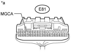
w/o Rear Heater:
Disconnect the air conditioning amplifier assembly connector.
Measure the voltage according to the value(s) in the table below.
- Standard Voltage:
Tester Connection
| Switch Condition
| Specified Condition
|
E81-17 (MGCA) - Body ground
| Ignition switch off
| Below 1 V
|
E81-17 (MGCA) - Body ground
| Ignition switch ON
| 11 to 14 V
|
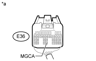
Text in Illustration*a
| Rear view of wire harness connector
(to Air Conditioning Amplifier Assembly)
|
| | REPAIR OR REPLACE HARNESS OR CONNECTOR |
|
|
| 8.CHECK HARNESS AND CONNECTOR (VISCOUS HEATER RELAY - VISCOUS WITH MAGNET CLUTCH HEATER ASSEMBLY AND BATTERY) |
- *1: for LHD
- *2: for RHD
Disconnect the 1Q, 1Y*1 or 1K*2 No. 1 engine room relay block connector.
Disconnect the C98 viscous with magnet clutch heater assembly connector
Measure the resistance according to the value(s) in the table below.
- Standard Resistance:
Tester Connection
| Condition
| Specified Condition
|
1Q-2 - C98- (MG+)
| Always
| Below 1 Ω
|
1Q-2 or C98- (MG+ - Body ground
| Always
| 10 kΩ or higher
|
Measure the voltage according to the value(s) in the table below.
- Standard Voltage:
- for LHD:
Tester Connection
| Condition
| Specified Condition
|
1Y-1 - Body ground
| Always
| 11 to 14 V
|
1Q-3 - Body ground
| Ignition switch off
| Below 1 V
|
1Q-3 - Body ground
| Ignition switch ON
| 11 to 14 V
|
- for RHD:
Tester Connection
| Condition
| Specified Condition
|
1K-1 - Body ground
| Always
| 11 to 14 V
|
1Q-3 - Body ground
| Ignition switch off
| Below 1 V
|
1Q-3 - Body ground
| Ignition switch ON
| 11 to 14 V
|
| | REPAIR OR REPLACE HARNESS OR CONNECTOR |
|
|
| 9.CHECK VISCOUS WITH MAGNET CLUTCH HEATER ASSEMBLY |
Replace the viscous with magnet clutch heater assembly with a new or known good one (Click here).
Check that the air conditioning system is operated normally.
- OK:
- Air conditioning system is operated normally.
| | REPLACE AIR CONDITIONING AMPLIFIER ASSEMBLY (Click here) |
|
|
| OK |
|
|
|
| END (VISCOUS WITH MAGNET CLUTCH HEATER ASSEMBLY WAS DEFECTIVE) |
|