Air Conditioning System (For Automatic Air Conditioning System) -- Terminals Of Ecu |
| CHECK AIR CONDITIONING AMPLIFIER ASSEMBLY (w/ Rear Heater) |

Disconnect the E36 and E35 air conditioning amplifier assembly connectors.
Measure the voltage and resistance according to the value(s) in the table below.
Terminal No. (Symbol) Wiring Color Terminal Description Condition Specified Condition E35-6 (E1) - Body ground W-B - Body ground Ground Always Below 1 Ω E35-17 (RHTR) - E35-31 (SGND) W - GR Power supply for duct sensor RH - Ignition switch ON
- Passenger side duct sensor temperature: 25°C (77°F)
4850 to 5150 Ω E35-18 (RHTL) - E35-31 (SGND) V - GR Power supply for duct sensor LH - Ignition switch ON
- Passenger side duct sensor temperature: 25°C (77°F)
4850 to 5150 Ω E36-1 (GND) - Body ground BR - Body ground Ground Always Below 1 Ω E36-5 (IG+) - E36-1 (GND) G - BR Ignition power supply Ignition switch ON 11 to 14 V Ignition switch off Below 1 V E36-6 (+B1) - E36-1 (GND) LG - BR Battery power supply Always 11 to 14 V E36-7 (+B2) - E36-1 (GND) LG - BR Battery power supply Always 11 to 14 V - Ignition switch ON
Reconnect the E36 and E35 air conditioning amplifier assembly connectors.
Measure the voltage and resistance according to the value(s) in the table below.
Terminal No. (Symbol) Wiring Color Terminal Description Condition Specified Condition E35-1 (SG-1) - Body ground B - Body ground Ground for room temperature sensor (for front) Always Below 1 Ω E35-9 (PRE) - E35-32 (SG-2) R - G Air conditioning pressure sensor signal - Ignition switch ON
- A/C switch off
0.63 to 4.78 V - Engine idling
- A/C switch on
- Blower switch LO
- Refrigerant pressure is normal
0.63 to 4.78 V Refrigerant pressure: Abnormal (less than 177 kPa [1.8 kgf/cm2, 26 psi]) Below 0.63 V Refrigerant pressure: Abnormal (more than 3079 kPa [31.4 kgf/cm2, 446 psi]) 4.78 V or higher E35-10 (TAM) - E35-32 (SG-2) V - G Ambient temperature sensor signal - Ignition switch ON
- Ambient temperature: 25°C (77°F)
1.4 to 1.6 V - Ignition switch ON
- Ambient temperature: 50°C (122°F)
0.7 to 0.9 V E35-11 (TEC) - E35-33 (SG) W - P Evaporator temperature sensor signal (for rear) - Ignition switch ON
- Evaporator temperature: 15°C (59°F)
1.4 to 1.8 V E35-13 (S5-3) - E35-32 (SG-2) LG - G Power supply for air conditioner pressure Ignition switch ON 4.75 to 5.25 V E35-16 (TR) - E35-1 (SG-1) W - B Room temperature sensor signal (for front) - Ignition switch ON
- Front side interior temperature: 25°C (77°F)
1.9 to 2.1 V Room temperature sensor signal (for front) - Ignition switch ON
- Front side interior temperature: 50°C (122°F)
1.0 to 2.0 V E35-21 (TR) - E35-33 (SG) R - P Room temperature sensor signal (for rear LH) - Ignition switch ON
- Vehicle interior temperature: 25°C (77°F)
1.9 to 2.1 V - Ignition switch ON
- Vehicle interior temperature: 50°C (122°F)
1.0 to 1.2 V E35-22 (TSET) - E35-33 (SG) R - P Room temperature sensor signal (for rear RH) - Ignition switch ON
- Vehicle interior temperature: 25°C (77°F)
1.9 to 2.1 V - Ignition switch ON
- Vehicle interior temperature: 50°C (122°F)
1.0 to 1.2 V E35-28 (SW 1) - Body ground*1 P - Body ground Idle up switch operation signal - Engine running
- A/C switch on
- Blower switch on (LO level)
- Idle up switch off → on
Below 1 V 14 V E35-29 (COOL) - Body ground*4 W - Body ground Cool box operation signal - Ignition switch ON
- Cool box switch on
Below 1 V - Ignition switch ON
- Cool box switch off
11 to 14 V E35-30 (LOCK) - E35-32 (SG-2) L - G Compressor lock sensor signal - Engine idling
- A/C switch on (magnet clutch on)
- Blower switch: LO
Pulse generation
(see waveform 1)E35-31 (SGND) - Body ground GR - Body ground Ground for duct sensor RH Always Below 1 Ω E35-32 (SG-2) - Body ground G - Body ground Ground for pressure sensor, cooler compressor Always Below 1 Ω E35-33 (SG) - Body ground P - Body ground Ground for evaporator temperature sensor signal (for rear), rear room temperature sensor signal LH and RH Always Below 1 Ω E36-3 (BLW) - E36-1 (GND) R - BR Blower motor control signal - Ignition switch ON
- Blower switch: LO
Pulse generation
(see waveform 2)- Ignition switch ON
- Blower switch: off
4.5 to 5.5 V E36-8 (PTC1) - Body ground*2 W - Body ground Quick heater assembly operation signal - Engine idling
- Set temperature: MAX HOT (HI)
- Engine coolant temperature: Below 65°C (149°F)
- Ambient temperature: Below 10°C (50°F)
- Blower switch: off → on (after 10 seconds)
11 to 14 V → Below 1 V E36-11 (AC1) - Body ground L - Body ground Compressor operation signal - Engine idling
- Blower switch LO
- A/C switch off
11 to 14 V - Engine idling
- Blower switch LO
- A/C switch on
Below 1 V E36-12 (RBUG) - Body ground BR - Body ground Ground for BUS IC (for rear) Always Below 1 Ω E36-13 (RBUS) - E36-12 (RBUG) R - BR BUS IC control signal (for rear) Ignition switch ON Pulse generation E36-14 (RBBU) - E36-12 (RBUG) L - BR Power supply for BUS IC (for rear) Always 11 to 14 V E36-17 (BLWH) - E36-1 (GND) L - BR Blower motor control signal (for rear) - Ignition switch ON
- Blower switch: LO
Pulse generation
(see waveform 3)E36-18 (MGC) - E36-1 (GND) R - BR Magnet clutch operation signal - Engine idling
- Blower switch: LO
- A/C switch on (magnet clutch on)
Below 1 V - Engine idling
- Blower switch: LO
- A/C switch on or off (magnet clutch off)
11 to 14 V E36-19 (RMGV) - E36-1 (GND) B - BR Rear cooling unit expansion valve signal - Ignition switch ON
- Blower switch LO
- A/C switch on
11 to 14 V E36-22 (ACT) - Body ground G - Body ground Compressor operation signal - Engine idling
- A/C switch off or on (magnet clutch off)
Below 1 V - Engine idling
- A/C switch on (magnet clutch on)
11 to 14 V E36-23 (ALT) - Body ground R - Body ground Generator assembly signal Ignition switch ON Pulse generation E36-24 (PTC3) - Body ground*2 R - Body ground Quick heater assembly operation signal - Engine idling
- Set temperature: MAX HOT (HI)
- Engine coolant temperature: Below 65°C (149°F)
- Ambient temperature: Below 10°C (50°F)
- Blower switch: off → on (after 20 seconds)
11 to 14 V → Below 1 V E36-26 (PTC2) - Body ground*2 B - Body ground Quick heater assembly operation signal - Engine idling
- Set temperature: MAX HOT (HI)
- Engine coolant temperature: Below 65°C (149°F)
- Ambient temperature: Below 10°C (50°F)
- Blower switch: off → on (after 30 seconds)
11 to 14 V → Below 1 V E36-27 (CFN+) - Body ground*3 R - Body ground Condenser fan operation signal Ignition switch ON 11 to 14 V E36-29 (ECOS) - Body ground*5 B - Body ground Integration control and panel assembly (ECO mode switch) operation signal - Ignition switch ON
- Integration control and panel assembly (ECO mode switch) on
Below 1 V - Ignition switch ON
- Integration control and panel assembly (ECO mode switch) off
11 to 14 V E36-32 (MGCA) - Body ground*1 P - Body ground Viscous with magnet clutch operation signal - Engine idling
- Idle up switch on
Below 1 V z72-1 (BUS G) - Body ground - Ground for BUS IC (for front) Always Below 1 Ω z72-2 (BUS) - z72-1 (BUS G) - BUS IC control signal (for front) Ignition switch ON Pulse generation z72-3 (B BUS) - z72-1 (BUS G) - Power supply for BUS IC (for front) Always 11 to 14 V z72-11 (TE) - z72-12 (SG) - Evaporator temperature sensor signal - Ignition switch ON
- Evaporator temperature: 15°C (59°F)
1.0 to 1.2 V z72-12 (SG) - Body ground - Ground for evaporator temperature sensor Always Below 1 Ω - *1: w/ Viscous Heater
- *2: w/ PTC Heater
- *3: w/ Condenser Fan
- *4: w/ Cool Box
- *5: w/ ECO Mode Switch
- Ignition switch ON
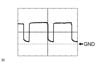
Using an oscilloscope, check waveform 1.
- HINT:
- When the engine speed is increased, the duty ratio changes accordingly.
Item Content Terminal No. (Symbol) E35-30 (LOCK) - E35-32 (SG-2) Tool Setting 200 mV/DIV., 10 ms/DIV. Condition - Engine idling
- A/C switch on (magnet clutch on)
- Blower switch: LO
Using an oscilloscope, check waveform 2.
- HINT:
- When the blower level is increased, the duty ratio changes accordingly.
Item Content Terminal No. (Symbol) E36-3 (BLW) - E36-1 (GND) Tool Setting 1 V/DIV., 500 μs/DIV. Condition - Ignition switch ON
- Blower switch: LO
Using an oscilloscope, check waveform 3.
- HINT:
- When the rear blower level is increased, the duty ratio changes accordingly.
Item Content Terminal No. (Symbol) E36-17 (BLWH) - E36-1 (GND) Tool Setting 2 V/DIV., 500 μs/DIV. Condition - Ignition switch ON
- Blower switch: LO
 |
 |
 |
| CHECK AIR CONDITIONING AMPLIFIER ASSEMBLY (w/o Rear Heater) |
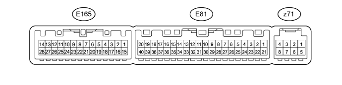
Disconnect the E81 air conditioning amplifier assembly connector.
Measure the voltage and resistance according to the value(s) in the table below.
Terminal No. (Symbol) Wiring Color Terminal Description Condition Specified Condition E81-1 (IG+) - E81-14 (GND) G - BR Ignition power supply Ignition switch ON 11 to 14 V Ignition switch off Below 1 V E81-14 (GND) - Body ground BR - Body ground Ground Always Below 1 Ω E81-21 (+B1) - E81-14 (GND) LG - BR Battery power supply Always 11 to 14 V Reconnect the E81 air conditioning amplifier assembly connector.
Measure the voltage, resistance and waveform according to the value(s) in the table below.
Terminal No. (Symbol) Wiring Color Terminal Description Condition Specified Condition E81-3 (PTC2) - Body ground*2 B - Body ground Quick heater assembly operation signal - Engine idling
- Set temperature: MAX HOT (HI)
- Engine coolant temperature: Below 65°C (149°F)
- Ambient temperature: Below 10°C (50°F)
- Blower switch: off → on (after 30 seconds)
11 to 14 V → Below 1 V E81-4 (SW 1) - Body ground*1 P - Body ground Idle up switch operation signal - Engine running
- A/C switch on
- Blower switch on (LO level)
- Idle up switch off → on
Below 1 V 14 V E81-5 (TAM) - E81-13 (SG-2) V - G Ambient temperature sensor signal - Ignition switch ON
- Ambient temperature: 25°C (77°F)
1.4 to 1.6 V - Ignition switch ON
- Ambient temperature: 50°C (122°F)
0.7 to 0.9 V E81-8 (LOCK) - E81-13 (SG-2) L - G Compressor lock sensor signal - Engine idling
- A/C switch on (magnet clutch on)
- Blower switch: LO
Pulse generation
(see waveform 1)E81-9 (PRE) - E81-13 (SG-2) R - G Air conditioning pressure sensor signal - Ignition switch ON
- A/C switch off
0.63 to 4.78 V - Engine idling
- A/C switch on
- Blower switch LO
- Refrigerant pressure is normal
0.63 to 4.78 V Refrigerant pressure: Abnormal (less than 177 kPa [1.8 kgf/cm2, 26 psi]) Below 0.63 V Refrigerant pressure: Abnormal (more than 3079 kPa [31.4 kgf/cm2, 446 psi]) 4.78 V or higher E81-13 (SG-2) - Body ground G - Body ground Ground for pressure sensor, cooler compressor Always Below 1 Ω E81-17 (MGCA) - Body ground*1 P - Body ground Viscous with magnet clutch operation signal - Engine idling
- Idle up switch on
Below 1 V E81-18 (RCRL) - Body ground B - Body ground Rear cooler control relay operation signal - Ignition switch ON
- Rear blower switch off
Below 1 V - Ignition switch ON
- Rear blower switch LO
11 to 14 V E81-19 (CFN+) - Body ground*3 R - Body ground Condenser fan operation signal Ignition switch ON 11 to 14 V E81-20 (MGC) - E81-14 (GND) R - BR Magnet clutch operation signal - Engine idling
- Blower switch: LO
- A/C switch on (magnet clutch on)
Below 1 V - Engine idling
- Blower switch: LO
- A/C switch on or off (magnet clutch off)
11 to 14 V E81-22 (BLW) - E81-14 (GND) R - BR Blower motor control signal - Ignition switch ON
- Blower switch: LO
Pulse generation
(see waveform 2)- Ignition switch ON
- Blower switch: off
4.5 to 5.5 V E81-23 (AC1) - Body ground L - Body ground Compressor operation signal - Engine idling
- Blower switch LO
- A/C switch off
11 to 14 V - Engine idling
- Blower switch LO
- A/C switch on
Below 1 V E81-24 (COOL) - Body ground*4 W - Body ground Cool box operation signal - Ignition switch ON
- Cool box switch on
Below 1 V - Ignition switch ON
- Cool box switch off
11 to 14 V E81-25 (ALT) - Body ground R - Body ground Generator assembly signal Ignition switch ON Pulse generation E81-27 (ACT) - Body ground G - Body ground Compressor operation signal - Engine idling
- A/C switch off or on (magnet clutch off)
Below 1 V - Engine idling
- A/C switch on (magnet clutch on)
11 to 14 V E81-30 (S5-3) - E81-13 (SG-2) LG - G Power supply for air conditioner pressure Ignition switch ON 4.75 to 5.25 V E81-36 (PTC3) - Body ground*2 R - Body ground Quick heater assembly operation signal - Engine idling
- Set temperature: MAX HOT (HI)
- Engine coolant temperature: Below 65°C (149°F)
- Ambient temperature: Below 10°C (50°F)
- Blower switch: off → on (after 20 seconds)
11 to 14 V → Below 1 V E81-40 (PTC1) - Body ground*2 W - Body ground Quick heater assembly operation signal - Engine idling
- Set temperature: MAX HOT (HI)
- Engine coolant temperature: Below 65°C (149°F)
- Ambient temperature: Below 10°C (50°F)
- Blower switch: off → on (after 10 seconds)
11 to 14 V → Below 1 V E165-4 (TR) - E165-8 (SG-1) W - B Room temperature sensor signal - Ignition switch ON
- Front side interior temperature: 25°C (77°F)
1.9 to 2.1 V Room temperature sensor signal - Ignition switch ON
- Front side interior temperature: 50°C (122°F)
1.0 to 2.0 V E165-6 (ECOS) - Body ground*5 B - Body ground Integration control and panel assembly (ECO mode switch) operation signal - Ignition switch ON
- Integration control and panel assembly (ECO mode switch) on
Below 1 V - Ignition switch ON
- Integration control and panel assembly (ECO mode switch) off
11 to 14 V E165-8 (SG-1) - Body ground B - Body ground Ground for room temperature sensor Always Below 1 Ω z71-2 (BUS G) - Body ground - Ground for BUS IC Always Below 1 Ω z71-3 (BUS) - z71-2 (BUS G) - BUS IC control signal Ignition switch ON Pulse generation z71-4 (B BUS) - z71-2 (BUS G) - Power supply for BUS IC Always 11 to 14 V z71-5(SG) - Body ground - Ground for evaporator temperature sensor Always Below 1 Ω z71-5 (GS) - z71-6 (TE) - Evaporator temperature sensor signal - Ignition switch ON
- Evaporator temperature: 15°C (59°F)
1.0 to 1.2 V - *1: w/ Viscous Heater
- *2: w/ PTC Heater
- *3: w/ Condenser Fan
- *4: w/ Cool Box
- *5: w/ ECO Mode Switch
- Engine idling
Using an oscilloscope, check waveform 1.
Compressor Lock Sensor Signal Item Content Terminal No. (Symbol) E81-8 (LOCK) - E81-13 (SG-2) Tool Setting 200 mV/DIV., 10 ms/DIV. Condition - Engine idling
- Blower switch: LO
- A/C switch: On
- HINT:
- When the rear blower level is increased, the duty ratio changes accordingly.
- Engine idling
Using an oscilloscope, check waveform 2.
Blower Motor Control Signal Item Content Terminal No. (Symbol) E81-22 (BLW) - E81-14 (GND) Tool Setting 1 V/DIV., 500 μs/DIV. Condition - Ignition switch ON
- Blower switch: LO
- HINT:
- When the blower level is increased, the duty ratio changes accordingly.
- Ignition switch ON
 |
|
| CHECK AIR CONDITIONING CONTROL ASSEMBLY (w/o Navigation System [w/o Entry and Start System]) |

Disconnect the F10 air conditioning control assembly connector.
Measure the resistance and voltage according to the value(s) in the table below.
Terminal No. (Symbol) Wiring Color Terminal Description Condition Specified Condition F10-7 (IG+) - F10-1 (GND) B - W-B Ignition power supply Ignition switch ON 11 to 14 V Ignition switch off Below 1 V F10-1 (GND) - Body ground W-B - Body ground Ground Always Below 1 Ω Reconnect the F10 air conditioning control assembly connector.
Measure the resistance and voltage according to the value(s) in the table below.
Terminal No. (Symbol) Wiring Color Terminal Description Condition Specified Condition F10-12 (DTP+) - F10-1 (GND) GR - W-B Temperature up switch signal Temperature up switch not pressed Below 1 V Temperature up switch pressed Alternating between 3.5 V or higher and below 1 V F10-10 (PTP+) - F10-1 (GND) L - W-B Temperature up switch signal Temperature up switch not pressed Below 1 V Temperature up switch pressed Alternating between 3.5 V or higher and below 1 V F10-9 (S5) - F10-1 (GND) SB - W-B Signal ground Always Below 1 Ω F10-11 (DTP-) - F10-1 (GND) B - W-B Temperature down switch signal Temperature down switch not pressed Below 1 V Temperature down switch pressed Alternating between 3.5 V or higher and below 1 V F10-3 (PTP-) - F10-1 (GND) V - W-B Temperature down switch signal Temperature down switch not pressed Below 1 V Temperature down switch pressed Alternating between 3.5 V or higher and below 1 V F10-2 (SG) - F10-1 (GND) R - W-B Signal ground Always Below 1 Ω
| CHECK AIR CONDITIONING CONTROL ASSEMBLY (w/o Navigation System [w/ Entry and Start System]) |
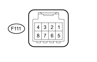 |
Disconnect the F111 air conditioning control assembly connector.
Measure the resistance and voltage according to the value(s) in the table below.
Terminal No. (Symbol) Wiring Color Terminal Description Condition Specified Condition F111-5 (IG+) - F111-8 (GND) B - W-B Ignition power supply Ignition switch ON 11 to 14 V Ignition switch off Below 1 V F111-8(GND) - Body ground W-B - Body ground Ground Always Below 1 Ω
| CHECK NO. 2 AIR CONDITIONING CONTROL ASSEMBLY (w/ Rear Heater) |
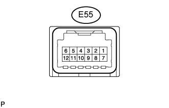 |
Disconnect the E55 No. 2 air conditioning control assembly connector.
Measure the resistance and voltage according to the value(s) in the table below.
Terminal No. (Symbol) Wiring Color Terminal Description Condition Specified Condition E55-6 (IG) - E55-1 (E) B - W-B Ignition power supply Always 11 to 14 V E55-1 (E) - Body ground W-B - Body ground Ground Always Below 1 Ω
| MULTI-DISPLAY ASSEMBLY (w/ Navigation System) (Click here) |
| MULTI-MEDIA MODULE RECEIVER ASSEMBLY (w/ Navigation System) (Click here) |