Dtc C1A4B Stop Light Relay Circuit
DESCRIPTION
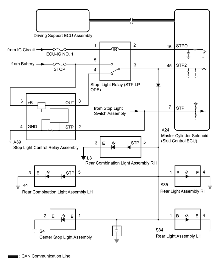
WIRING DIAGRAM
INSPECTION PROCEDURE
CHECK STOP LIGHT OPERATION
CHECK HARNESS AND CONNECTOR (MASTER CYLINDER SOLENOID [SKID CONTROL ECU] STPO TERMINAL VOLTAGE)
CHECK HARNESS AND CONNECTOR (MASTER CYLINDER SOLENOID [SKID CONTROL ECU] STP2 TERMINAL VOLTAGE)
PERFORM ACTIVE TEST USING GTS (STOP LIGHT RELAY)
INSPECT STOP LIGHT RELAY (STP LP OPE)
CHECK HARNESS AND CONNECTOR (STOP LIGHT RELAY [STP LP OPE] - BATTERY)
CHECK HARNESS AND CONNECTOR (STOP LIGHT RELAY [STP LP OPE] - MASTER CYLINDER SOLENOID [SKID CONTLOR ECU] AND BATTERY)
DTC C1A4B Stop Light Relay Circuit |
DESCRIPTION
The master cylinder solenoid (skid control ECU) sends a stop light operation request signal to the stop light relay (STP LP OPE). If the master cylinder solenoid (skid control ECU) detects a malfunction in the stop light relay circuit, the driving support ECU assembly stores DTC C1A4B.
| Vehicle Condition
|
Pattern 1
| Pattern 2
|
Diagnosis Condition
| IG1 terminal voltage is 11 to 14 V
| ○
| ○
|
Stop Light illumination output (STPO) ON
| ○
| -
|
Stop Light illumination output (STPO) OFF
| -
| ○
|
Malfunction Status
| No signal input to STP2 terminal
| ○
| -
|
Signals input to STP and STP2 terminals do not match
| -
| ○
|
Malfunction Time
| 0.3 seconds or more
| 0.3 seconds or more
|
Number of Trips
| -
| -
|
DTC No.
| DTC Detection Condition
| Trouble Area
|
C1A4B
| Either of the following conditions is met:
- When the engine switch is on (IG), the IG1 terminal voltage is between 11 and 14 V and the stop light illumination output signal (STPO) is output, the signal is not received at terminal STP2 for 0.3 seconds or more.
- When the stop light illumination output (STPO) signal is off, signals input to the STP terminal and STP2 terminal of the master cylinder solenoid (skid control ECU) differ for 0.3 seconds or more continuously.
| - Lighting system
- Stop light relay (STP LP OPE)
- Master cylinder solenoid (Skid control ECU)
- Harness or connector
|
WIRING DIAGRAM
INSPECTION PROCEDURE
- NOTICE:
- Inspect the fuses for circuits related to this system before performing the following procedure.
- After replacing the master cylinder solenoid, perform zero point calibration and store the system information (Click here).
- When the start function does not operate, check the Entry and Start System(for start function) (Click here).
| 1.CHECK STOP LIGHT OPERATION |
Check that the stop lights come on when the brake pedal is depressed and go off when the brake pedal is released.
- OK:
- The stop lights illuminate when the brake pedal is depressed. The stop lights turn off when the brake pedal is released.
| 2.CHECK HARNESS AND CONNECTOR (MASTER CYLINDER SOLENOID [SKID CONTROL ECU] STPO TERMINAL VOLTAGE) |
Disconnect the master cylinder solenoid (skid control ECU) connector.
Measure the voltage according to the value(s) in the table below.
- Standard Voltage:
Tester Connection
| Condition
| Specified Condition
|
A24-16 (STPO) - Body ground
| Engine switch on (IG)
| 11 to 14 V
|
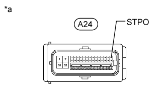
Text in Illustration *a
| Front view of wire harness connector
(to Master Cylinder Solenoid [Skid Control ECU])
|
| 3.CHECK HARNESS AND CONNECTOR (MASTER CYLINDER SOLENOID [SKID CONTROL ECU] STP2 TERMINAL VOLTAGE) |
Disconnect the master cylinder solenoid (skid control ECU) connector.
Measure the voltage according to the value(s) in the table below.
- Standard Voltage:
Tester Connection
| Condition
| Specified Condition
|
A24-45 (STP2) - Body ground
| Brake pedal depressed
| 11 to 14 V
|
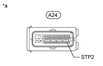
Text in Illustration *a
| Front view of wire harness connector
(to Master Cylinder Solenoid [Skid Control ECU])
|
| | REPAIR OR REPLACE HARNESS OR CONNECTOR |
|
|
| 4.PERFORM ACTIVE TEST USING GTS (STOP LIGHT RELAY) |
Enter the following menus: Chassis / ABS/VSC/TRAC / Active Test.
Perform the Active Test according to the display on the GTS.
ABS/VSC/TRAC Tester Display
| Test Part
| Control Range
| Diagnostic Note
|
Stop Light Relay
| Stop light relay (STP LP OPE)
| Relay ON/OFF
| Observe the stop light (the stop lights do not come on for 2 to 5 seconds).
|
Check the stop light relay (STP LP OPE) operation using the Data List and stop light operation by performing an Active Test.
ABS/VSC/TRAC Tester Display
| Measurement Item/Range
| Normal Condition
| Diagnostic Note
|
Stop Light Relay Output
| Stop light relay (STP LP OPE) output/ ON or OFF
| ON: Relay output on (Stop light on)
OFF: Relay output off (Stop light off)
| -
|
ResultResult
| Proceed to
|
The Data List item "Stop Light Relay Output" switches between ON and OFF when turning the stop light control relay on and off with the Active Test, but the stop lights do not illuminate or turn off
| A
|
The Data List item "Stop Light Relay Output" does not switch between ON and OFF when turning the stop light control relay on and off with the Active Test (for LHD)
| B
|
The Data List item "Stop Light Relay Output" switches between ON and OFF when turning the stop light control relay on and off with the Active Test and the stop lights illuminate and turn off (for LHD)
|
The Data List item "Stop Light Relay Output" does not switch between ON and OFF when turning the stop light control relay on and off with the Active Test (for RHD)
| C
|
The Data List item "Stop Light Relay Output" switches between ON and OFF when turning the stop light control relay on and off with the Active Test and the stop lights illuminate and turn off (for RHD)
|
| | REPLACE MASTER CYLINDER SOLENOID (SKID CONTROL ECU) (Click here) |
|
|
| | REPLACE MASTER CYLINDER SOLENOID (SKID CONTROL ECU) (Click here) |
|
|
| 5.INSPECT STOP LIGHT RELAY (STP LP OPE) |
Turn the engine switch off.
Remove the stop light relay (STP LP OPE) from the engine room relay block and junction block assembly.
Inspect the stop light relay (STP LP OPE) (Click here).
| | REPLACE STOP LIGHT RELAY (STP LP OPE) |
|
|
| 6.CHECK HARNESS AND CONNECTOR (STOP LIGHT RELAY [STP LP OPE] - BATTERY) |
Turn the engine switch off.
Remove the stop light relay (STP LP OPE) from the engine room relay block and junction block assembly.
Measure the voltage according to the value(s) in the table below.
- Standard Voltage:
Tester Connection
| Condition
| Specified Condition
|
Stop light relay (STP LP OPE) holder terminal 5 - Body ground
| Always
| 11 to 14 V
|
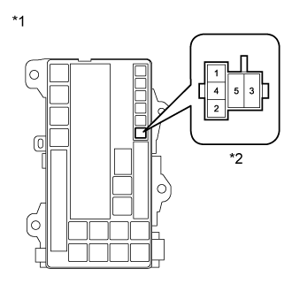
Text in Illustration *1
| Engine Room Relay Block and Junction Block Assembly
|
*2
| Stop Light Relay (STP LP OPE) Holder Terminal
|
- OK:
Result
| Proceed to
|
OK (for LHD)
| A
|
OK (for RHD)
| B
|
NG
| C
|
| | REPLACE MASTER CYLINDER SOLENOID (SKID CONTROL ECU) (Click here) |
|
|
| | REPAIR OR REPLACE HARNESS OR CONNECTOR |
|
|
| A |
|
|
|
| REPLACE MASTER CYLINDER SOLENOID (SKID CONTROL ECU) (Click here) |
|
| 7.CHECK HARNESS AND CONNECTOR (STOP LIGHT RELAY [STP LP OPE] - MASTER CYLINDER SOLENOID [SKID CONTLOR ECU] AND BATTERY) |
Turn the engine switch off.
Remove the stop light relay (STP LP OPE) from the engine room relay block and junction block assembly.
Disconnect the A24 master cylinder solenoid (skid control ECU) connector.
Measure the resistance according to the value(s) in the table below.
- Standard Resistance:
Tester Connection
| Condition
| Specified Condition
|
Stop light relay (STP LP OPE) holder terminal 2 - A24-16 (STPO)
| Always
| Below 1 Ω
|
Stop light relay (STP LP OPE) holder terminal 2 or A24-16 (STPO) - Body ground
| Always
| 10 kΩ or higher
|
Measure the voltage according to the value(s) in the table below.
- Standard Voltage:
Tester Connection
| Switch Condition
| Specified Condition
|
Stop light relay (STP LP OPE) holder terminal 1 - Body ground
| Engine switch on (IG)
| 11 to 14 V
|
Text in Illustration *1
| Engine Room Relay Block and Junction Block Assembly
|
*2
| Stop Light Relay (STP LP OPE) Holder Terminal
|
| | REPAIR OR REPLACE HARNESS OR CONNECTOR |
|
|
| OK |
|
|
|
| REPLACE STOP LIGHT RELAY (STP LP OPE) |
|