DESCRIPTION
WIRING DIAGRAM
INSPECTION PROCEDURE
CHECK DTC
INSPECT LIGHTS
CHECK HARNESS AND CONNECTOR (TURN SIGNAL CIRCUIT RH)
INSPECT HEADLIGHT ASSEMBLY RH
INSPECT OUTER REAR VIEW MIRROR ASSEMBLY RH
CHECK VEHICLE TYPE
INSPECT REAR COMBINATION LIGHT SOCKET AND WIRE SUB-ASSEMBLY RH
CHECK VEHICLE TYPE
CHECK TOWING CONVERTER
CHECK HARNESS AND CONNECTOR (TURN SIGNAL CIRCUIT RH)
CHECK HARNESS AND CONNECTOR (TURN SIGNAL CIRCUIT RH)
CHECK HARNESS AND CONNECTOR (TURN SIGNAL CIRCUIT LH)
INSPECT HEADLIGHT ASSEMBLY LH
INSPECT OUTER REAR VIEW MIRROR ASSEMBLY LH
CHECK VEHICLE TYPE
INSPECT REAR COMBINATION LIGHT SOCKET AND WIRE SUB-ASSEMBLY LH
CHECK VEHICLE TYPE
CHECK TOWING CONVERTER
CHECK HARNESS AND CONNECTOR (TURN SIGNAL CIRCUIT LH)
CHECK HARNESS AND CONNECTOR (TURN SIGNAL CIRCUIT RH)
DTC B1507 Open in Turn Signal Circuit |
DTC B1508 Short in Turn Signal / Hazard Flasher Circuit |
DESCRIPTION
These DTCs are stored when the combination meter assembly detects an open in a turn signal light circuit, a short in a turn signal light circuit, or a short in the hazard warning light circuit.DTC No.
| DTC Detection Condition
| Trouble Area
|
B1507
| When IG voltage is 9.5 V or more and the following condition is detected:
- Open in turn signal light circuit
| - LED
- Bulb
- Harness or connector
- Outer rear view mirror assembly LH*3
- Outer rear view mirror assembly RH*3
- Outer mirror control ECU assembly LH*1*3
- Outer mirror control ECU assembly RH*1*3
- Rear combination light socket and wire subassembly LH*2
- Rear combination light socket and wire subassembly RH*2
- Towing Converter Assembly*4
- Combination meter assembly
|
B1508
| When IG voltage is 9.5 V or more and the following condition is detected:
- Short in turn signal light circuit or hazard warning light circuit
| - LED
- Bulb
- Harness or connector
- Outer rear view mirror assembly LH*3
- Outer rear view mirror assembly RH*3
- Outer mirror control ECU assembly LH*1*3
- Outer mirror control ECU assembly RH*1*3
- Rear combination light socket and wire subassembly LH*2
- Rear combination light socket and wire subassembly RH*2
- Towing Converter Assembly*4
- Combination meter assembly
|
- *1: w/ Retract Mirror
- *2: except Double Swing Out Type
- *3: for Outer Rear View Mirror
- *4: w/ Towing Package
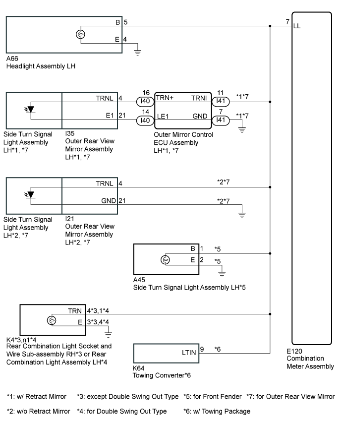
WIRING DIAGRAM
INSPECTION PROCEDURE
- NOTICE:
- Inspect the bulbs for this system before performing the following inspection procedure.
Clear the DTCs.
Recheck for DTCs and check that no DTCs are output.
ResultResult
| Proceed to
|
B1507 and B1508 are output
| A
|
B1507 and B1508 are not output
| B
|
Inspect the illumination of each turn signal light.
ResultResult
| Proceed to
|
RH side turn signal light does not illuminate
| A
|
LH side turn signal light does not illuminate
| B
|
| 3.CHECK HARNESS AND CONNECTOR (TURN SIGNAL CIRCUIT RH) |
- *1: w/ Retract Mirror
- *2: w/o Retract Mirror
- *3: except Double Swing Out Type
- *4: for Double Swing Out Type
- *5: for Front Fender
- *6: w/ Towing Package
- *7: for Outer Rear View Mirror
Disconnect the E120 combination meter assembly connector.
Disconnect the A69 headlight assembly RH connector.
Disconnect the I20*2 or I32*1 outer rear view mirror assembly RH connector.*7
Disconnect the A47 side turn signal light assembly RH connector.*5
Disconnect the L4*3 or Y1*4 rear combination light assembly RH connector.
Disconnect the K64 towing converter connector.*6
Measure the resistance according to the value(s) in the table below.
- Standard Resistance:
Tester Connection
| Condition
| Specified Condition
|
A69-5 (B) - E120-13 (LR)
| Always
| Below 1 Ω
|
A69-4 (E) - Body ground
| Always
| Below 1 Ω
|
I20-4 (TRNL) - E120-13 (LR)
| Always
| Below 1 Ω
|
I20-21 (GND) - Body ground
| Always
| Below 1 Ω
|
I32-4 (TRNR) - E120-13 (LR)
| Always
| Below 1 Ω
|
I32-21 (E1) - Body ground
| Always
| Below 1 Ω
|
A47-1 (B) - E120-13 (LR)
| Always
| Below 1 Ω
|
A47-2 (E) - Body ground
| Always
| Below 1 Ω
|
L4-4 (TRN) - E120-13 (LR)
| Always
| Below 1 Ω
|
L4-3 (E) - Body ground
| Always
| Below 1 Ω
|
Y1-1 (TRN) - E120-13 (LR)
| Always
| Below 1 Ω
|
Y1-4 (E) - Body ground
| Always
| Below 1 Ω
|
K64-3 (RTIN) - E120-13 (LR)
| Always
| Below 1 Ω
|
E120-13 (LR) - Body ground
| Always
| 10 kΩ or higher
|
- Result:
Result
| Proceed to
|
OK
| A
|
NG (for Outer Rear View Mirror with Retract Mirror)
| B
|
NG (except Outer Rear View Mirror with Retract Mirror)
| C
|
| |
|
| | REPAIR OR REPLACE HARNESS AND CONNECTOR |
|
|
| 4.INSPECT HEADLIGHT ASSEMBLY RH |
Remove the headlight assembly RH.
- for Halogen Headlight (Click here)
- for LED Headlight (Click here)
- for Halogen Headlight and LED Headlight (Click here)
Apply battery voltage between the terminals and check the light illumination condition.
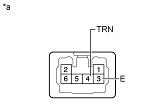
Text in Illustration*a
| Component without harness connected
(Headlight Assembly RH)
|
- OK:
Condition
| Specified Condition
|
Battery positive (+) →5 (B)
Battery positive (-) →4 (E)
| Turn signal light illuminates
|
- Result:
Result
| Proceed to
|
OK (for Outer Rear View Mirror)
| A
|
OK (for Front Fender)
| B
|
NG (for Halogen Headlight)
| C
|
NG (for LED Headlight)
| D
|
NG (for Halogen Headlight and LED Headlight)
| E
|
| 5.INSPECT OUTER REAR VIEW MIRROR ASSEMBLY RH |
Remove the outer rear view mirror assembly RH.
(Click here)
Inspect the outer rear view mirror assembly RH.
(Click here)
| | REPLACE OUTER REAR VIEW MIRROR ASSEMBLY RH (Click here) |
|
|
Check the vehicle type.
- Result:
Result
| Proceed to
|
except Double Swing Out Type
| A
|
for Double Swing Out Type
| B
|
| 7.INSPECT REAR COMBINATION LIGHT SOCKET AND WIRE SUB-ASSEMBLY RH |
Remove the rear combination light socket and wire subassembly RH (Click here).
Install the turn signal light bulb to the rear combination light socket and wire sub-assembly RH.
Apply battery voltage between the terminals and check the light illumination condition.
Text in Illustration*a
| Component without harness connected
(Rear Combination Light Socket and Wire Sub-assembly RH)
|
- OK:
Condition
| Specified Condition
|
Battery positive (+) →4 (TRN)
Battery positive (-) →3 (E)
| Turn signal light illuminates
|
| | REPLACE REAR COMBINATION LIGHT SOCKET AND WIRE SUB-ASSEMBLY RH (Click here) |
|
|
Check the vehicle type.
- Result:
Result
| Proceed to
|
w/ Towing Package
| A
|
w/o Towing Package
| B
|
Replace the towing converter.
Clear the DTCs.
Check for DTCs and check that no DTCs are output.
| OK |
|
|
|
| END (TOWING CONVERTER IS DEFECTIVE) |
|
| 10.CHECK HARNESS AND CONNECTOR (TURN SIGNAL CIRCUIT RH) |
- *1: except Double Swing Out Type
- *2: for Double Swing Out Type
- *3: w/ Towing Package
Disconnect the E120 combination meter assembly connector.
Disconnect the A69 headlight assembly RH connector.
Disconnect the I38 outer mirror control ECU assembly RH connector.
Disconnect the L4*1 or Y1*2 rear combination light assembly RH connector.
Disconnect the K64 towing converter connector.*3
Measure the resistance according to the value(s) in the table below.
- Standard Resistance:
Tester Connection
| Condition
| Specified Condition
|
A69-5 (B) - E120-13 (LR)
| Always
| Below 1 Ω
|
A69-4 (E) - Body ground
| Always
| Below 1 Ω
|
I38-11 (TRNI) - E120-13 (LR)
| Always
| Below 1 Ω
|
I38-7 (GND) - Body ground
| Always
| Below 1 Ω
|
L4-4 (TRN) - E120-13 (LR)
| Always
| Below 1 Ω
|
L4-3 (E) - Body ground
| Always
| Below 1 Ω
|
Y1-1 (TRN) - E120-13 (LR)
| Always
| Below 1 Ω
|
Y1-4 (E) - Body ground
| Always
| Below 1 Ω
|
K64-3 (RTIN) - E120-13 (LR)
| Always
| Below 1 Ω
|
E120-13 (LR) - Body ground
| Always
| 10 kΩ or higher
|
| | REPAIR OR REPLACE HARNESS AND CONNECTOR |
|
|
| 11.CHECK HARNESS AND CONNECTOR (TURN SIGNAL CIRCUIT RH) |
Disconnect the I37 outer mirror control ECU assembly RH connector.
Disconnect the I32 outer rear view mirror assembly RH connector.
Measure the resistance according to the value(s) in the table below.
- Standard Resistance:
Tester Connection
| Condition
| Specified Condition
|
I37-16 (TRN+) - I32-4 (TRNR)
| Always
| Below 1 Ω
|
I37-14 (RE1) - I32-21 (E1)
| Always
| Below 1 Ω
|
I37-16 (TRN+) or I32-4 (TRNR) - I37-14 (RE1) or I32-21 (E1)
| Always
| 10 kΩ or higher
|
| | REPAIR OR REPLACE HARNESS AND CONNECTOR |
|
|
| OK |
|
|
|
| REPLACE OUTER MIRROR CONTROL ECU ASSEMBLY RH (Click here) |
|
| 12.CHECK HARNESS AND CONNECTOR (TURN SIGNAL CIRCUIT LH) |
- *1: w/ Retract Mirror
- *2: w/o Retract Mirror
- *3: except Double Swing Out Type
- *4: for Double Swing Out Type
- *5: for Front Fender
- *6: w/ Towing Package
- *7: for Outer Rear View Mirror
Disconnect the E120 combination meter assembly connector.
Disconnect the A66 headlight assembly LH connector.
Disconnect the I21*2 or I35*1 outer rear view mirror assembly LH connector.*7
Disconnect the A45 side turn signal light assembly LH connector.*5
Disconnect the K4*3 or n1*4 rear combination light assembly LH connector.
Disconnect the K64 towing converter connector.*6
Measure the resistance according to the value(s) in the table below.
- Standard Resistance:
Tester Connection
| Condition
| Specified Condition
|
A66-5 (B) - E120-7 (LL)
| Always
| Below 1 Ω
|
A66-4 (E) - Body ground
| Always
| Below 1 Ω
|
I21-4 (TRNL) - E120-7 (LL)
| Always
| Below 1 Ω
|
I21-21 (GND) - Body ground
| Always
| Below 1 Ω
|
I35-4 (TRNL) - E120-7 (LL)
| Always
| Below 1 Ω
|
I35-21 (E1) - Body ground
| Always
| Below 1 Ω
|
A45-1 (B) - E120-7 (LL)
| Always
| Below 1 Ω
|
A45-2 (E) - Body ground
| Always
| Below 1 Ω
|
K4-4 (TRN) - E120-7 (LL)
| Always
| Below 1 Ω
|
K4-3 (E) - Body ground
| Always
| Below 1 Ω
|
n1-1 (TRN) - E120-7 (LL)
| Always
| Below 1 Ω
|
n1-4 (E) - Body ground
| Always
| Below 1 Ω
|
K64-9 (LTIN) - E120-7 (LL)
| Always
| Below 1 Ω
|
E120-7 (LL) - Body ground
| Always
| 10 kΩ or higher
|
- Result:
Result
| Proceed to
|
OK
| A
|
NG (for Outer Rear View Mirror with Retract Mirror)
| B
|
NG (except Outer Rear View Mirror with Retract Mirror)
| C
|
| |
|
| | REPAIR OR REPLACE HARNESS AND CONNECTOR |
|
|
| 13.INSPECT HEADLIGHT ASSEMBLY LH |
Remove the headlight assembly LH.
- for Halogen Headlight (Click here)
- for LED Headlight (Click here)
- for Halogen Headlight and LED Headlight (Click here)
Apply battery voltage between the terminals and check the light illumination condition.
Text in Illustration*a
| Component without harness connected
(Headlight Assembly LH)
|
- OK:
Condition
| Specified Condition
|
Battery positive (+) →5 (B)
Battery positive (-) →4 (E)
| Turn signal light illuminates
|
- Result:
Result
| Proceed to
|
OK (for Outer Rear View Mirror)
| A
|
OK (for Front Fender)
| B
|
NG (for Halogen Headlight)
| C
|
NG (for LED Headlight)
| D
|
NG (for Halogen Headlight and LED Headlight)
| E
|
| 14.INSPECT OUTER REAR VIEW MIRROR ASSEMBLY LH |
Remove the outer rear view mirror assembly LH.
(Click here)
Inspect the outer rear view mirror assembly LH.
(Click here)
| | REPLACE OUTER REAR VIEW MIRROR ASSEMBLY LH (Click here) |
|
|
Check the vehicle type.
- Result:
Result
| Proceed to
|
except Double Swing Out Type
| A
|
for Double Swing Out Type
| B
|
| 16.INSPECT REAR COMBINATION LIGHT SOCKET AND WIRE SUB-ASSEMBLY LH |
Remove the rear combination light socket and wire subassembly LH (Click here).
Install the turn signal light bulb to the rear combination light socket and wire sub-assembly LH.
Apply battery voltage between the terminals and check the light illumination condition.
Text in Illustration*a
| Component without harness connected
(Rear Combination Light Socket and Wire Sub-assembly LH)
|
- OK:
Condition
| Specified Condition
|
Battery positive (+) →4 (TRN)
Battery positive (-) →3 (E)
| Turn signal light illuminates
|
| | REAR COMBINATION LIGHT SOCKET AND WIRE SUB-ASSEMBLY LH (Click here) |
|
|
Check the vehicle type.
- Result:
Result
| Proceed to
|
w/ Towing Package
| A
|
w/o Towing Package
| B
|
| 18.CHECK TOWING CONVERTER |
Replace the towing converter.
Clear the DTCs.
Check for DTCs and check that no DTCs are output.
| OK |
|
|
|
| END (TOWING CONVERTER IS DEFECTIVE) |
|
| 19.CHECK HARNESS AND CONNECTOR (TURN SIGNAL CIRCUIT LH) |
- *1: except Double Swing Out Type
- *2: for Double Swing Out Type
- *3: w/ Towing Package
Disconnect the E120 combination meter assembly connector.
Disconnect the A66 headlight assembly LH connector.
Disconnect the I41 outer mirror control ECU assembly LH connector.
Disconnect the K4*1 or n1*2 rear combination light assembly LH connector.
Disconnect the K64 towing converter connector.*3
Measure the resistance according to the value(s) in the table below.
- Standard Resistance:
Tester Connection
| Condition
| Specified Condition
|
A66-5 (B) - E120-7 (LL)
| Always
| Below 1 Ω
|
A66-4 (E) - Body ground
| Always
| Below 1 Ω
|
I41-11 (TRNI) - E120-7 (LL)
| Always
| Below 1 Ω
|
I41-7 (GND) - Body ground
| Always
| Below 1 Ω
|
K4-4 (TRN) - E120-7 (LL)
| Always
| Below 1 Ω
|
K4-3 (E) - Body ground
| Always
| Below 1 Ω
|
n1-1 (TRN) - E120-7 (LL)
| Always
| Below 1 Ω
|
n1-4 (E) - Body ground
| Always
| Below 1 Ω
|
K64-9 (LTIN) - E120-7 (LL)
| Always
| Below 1 Ω
|
E120-7 (LL) - Body ground
| Always
| 10 kΩ or higher
|
| | REPAIR OR REPLACE HARNESS AND CONNECTOR |
|
|
| 20.CHECK HARNESS AND CONNECTOR (TURN SIGNAL CIRCUIT RH) |
Disconnect the I40 outer mirror control ECU assembly LH connector.
Disconnect the I35 outer rear view mirror assembly LH connector.
Measure the resistance according to the value(s) in the table below.
- Standard Resistance:
Tester Connection
| Condition
| Specified Condition
|
I40-16 (TRN+) - I35-4 (TRNL)
| Always
| Below 1 Ω
|
I40-14 (LE1) - I35-21 (E1)
| Always
| Below 1 Ω
|
I40-16 (TRN+) or I35-4 (TRNL) - I40-14 (LE1) or I35-21 (E1)
| Always
| 10 kΩ or higher
|
| | REPAIR OR REPLACE HARNESS AND CONNECTOR |
|
|
| OK |
|
|
|
| REPLACE OUTER MIRROR CONTROL ECU ASSEMBLY LH (Click here) |
|