Vehicle Interior. Land Cruiser. Urj200, 202 Grj200 Vdj200
Door Lock. Land Cruiser. Urj200, 202 Grj200 Vdj200
Wireless Door Lock Control System (W/O Entry And Start System) -- Terminals Of Ecu |
| CHECK MAIN BODY ECU |
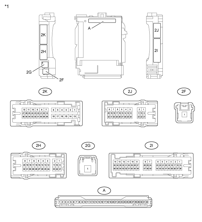
| *1 | Cowl Side Junction Block LH | - | - |
| *1 | Main Body ECU | - | - |
Remove the main body ECU from the cowl side junction block LH.
for LHD: Click here
for RHD: Click hereConnect the cowl side junction block LH connectors.
Measure the voltage and resistance according to the value(s) in the table below.
If the result is not as specified, there may be a malfunction on the wire harness side.Terminal No. (Symbol) Wiring Color Terminal Description Condition Specified Condition A-11 (GND1) - Body ground None - Body ground Ground Always Below 1 Ω A-30 (ACC) - Body ground None - Body ground ACC power supply ignition switch ACC 11 to 14 V ignition switch off Below 1 V A-31 (BECU) - Body ground None - Body ground Battery power supply Always 11 to 14 V A-32 (IG) - Body ground None - Body ground IG power supply ignition switch ON 11 to 14 V ignition switch off Below 1 V Install the main body ECU to the cowl side junction block LH.
for LHD: Click here
for RHD: Click hereMeasure the voltage according to the value(s) in the table below.
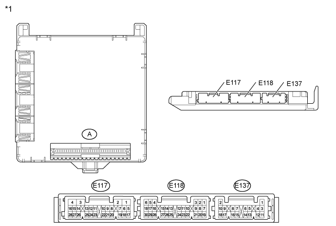
If the result is not as specified, the ECU may have a malfunction.Terminal No. (Symbol) Wiring Color Terminal Description Condition Specified Condition 2H-29 (BZR) - Body ground G - Body ground Wireless door lock buzzer signal Wireless door lock buzzer off Below 1 V Wireless door lock buzzer on Pulse generation 2J-16 (LSFR) - Body ground B - Body ground Front door RH unlock detection switch input signal Front door RH unlocked Below 1 V ignition switch off, all doors closed and front door RH locked Pulse generation 2J-19 (LSFL) - Body ground G - Body ground Front door LH unlock detection switch input signal Front door LH unlocked Below 1 V ignition switch off, all doors closed and front door LH locked Pulse generation 2J-28 (KSW) - Body ground G - Body ground Key unlock warning switch input No key in ignition key cylinder Pulse generation Key in ignition key cylinder Below 1 V 2J-29 (RCTY) - Body ground BE - Body ground Rear door courtesy light switch assembly RH input signal Rear door RH open Below 1 V Rear door RH closed Pulse generation 2K-31 (BCTY) - Body ground W - Body ground Back door courtesy light switch input Back door closed Below 1 V Back door open Pulse generation 2K-33 (LSWL) - Body ground L - Body ground Rear door LH unlock detection switch input signal Rear door LH unlocked Below 1 V ignition switch off, all doors closed and rear door LH locked Pulse generation 2K-34 (LCTY) - Body ground BE - Body ground Rear door courtesy light switch assembly LH input signal Rear door LH open Below 1 V Rear door LH closed Pulse generation E117-2 (LSWR) - Body ground W - Body ground Rear door RH unlock detection switch input signal Rear door RH unlocked Below 1 V ignition switch off, all doors closed and rear door RH locked 11 to 14 V E118-4 (RDA) - Body ground G - Body ground Door control receiver input No key in ignition key cylinder, all doors closed and transmitter switch off → on Pulse generation E118-5 (PRG) - Body ground L - Body ground Door control receiver output Key in ignition key cylinder → No key in ignition key cylinder Pulse generation E118-6 (FLCY) - Body ground V - Body ground Front door courtesy light switch assembly LH input signal Front door LH open Below 1 V Front door LH closed Pulse generation E118-17 (LSWB) - Body ground B - Body ground Back door unlock detection switch input signal Back door unlocked Below 1 V ignition switch off, all doors closed and back door locked 11 to 14 V E118-27 (FRCY) - Body ground V - Body ground Front door courtesy light switch assembly RH input signal Front door RH open Below 1 V Front door RH closed Pulse generation
| CHECK DOOR CONTROL RECEIVER |
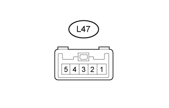 |
Disconnect the L47 receiver connector.
Measure the resistance and voltage according to the value(s) in the table below.
Terminal No. (Symbol) Wiring Color Terminal Description Condition Specified Condition L47-1 (GND) - Body ground BR - Body ground Ground Always Below 1 Ω L47-5 (+B) - Body ground R - Body ground Battery power supply Always 4.6 to 5.4 V - If the result is not as specified, there may be a malfunction on the wire harness side.
- If the result is not as specified, there may be a malfunction on the wire harness side.