Dtc B1206 P/W Master Switch Communication Stop
Networking. Land Cruiser. Urj200, 202 Grj200 Vdj200
DESCRIPTION
WIRING DIAGRAM
INSPECTION PROCEDURE
CLEAR DTC
CHECK FOR DTC
CHECK HARNESS AND CONNECTOR (MAIN BODY ECU [MULTIPLEX NETWORK
BODY ECU] - MULTIPLEX NETWORK MASTER
SWITCH ASSEMBLY
CHECK HARNESS AND CONNECTOR (MULTIPLEX NETWORK MASTER
SWITCH ASSEMBLY BATTERY AND BODY GROUND
REPLACE MULTIPLEX NETWORK MASTER SWITCH ASSEMBLY
CHECK FOR DTC
CHECK HARNESS AND CONNECTOR (COWL SIDE JUNCTION BLOCK LH - MULTIPLEX NETWORK MASTER SWITCH ASSEMBLY)
DTC B1206 P/W Master Switch Communication Stop |
DESCRIPTION
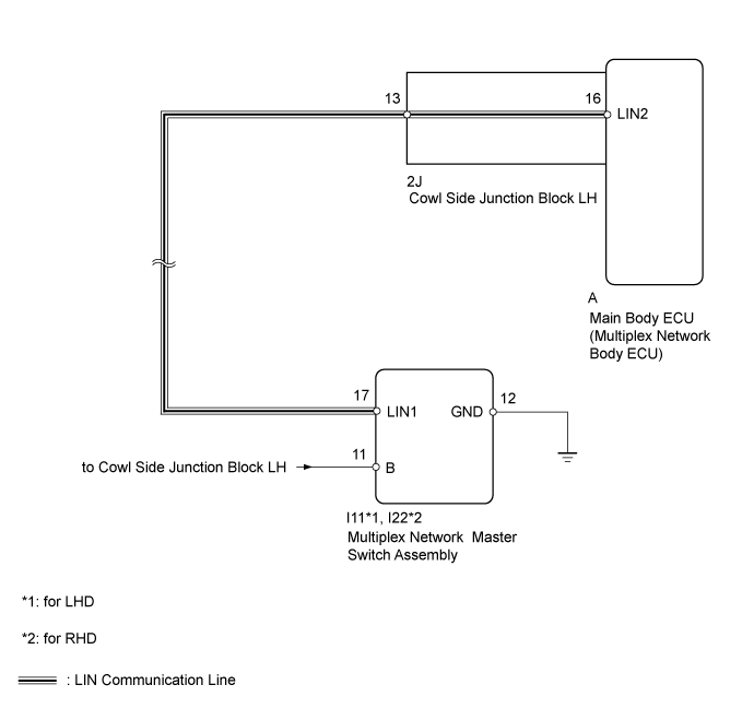
This DTC is stored when LIN communication between the multiplex network master Switch assembly and main body ECU (multiplex network body ECU) stops for 10 seconds or more.DTC Code
| DTC Detection Condition
| Trouble Area
|
B1206
| No communication between multiplex network master switch assembly and main body ECU (multiplex network body ECU) for 10 seconds or more.
| - Multiplex network master switch assembly
- Main body ECU (multiplex network body ECU)
- Cowl side junction block LH
- Harness or connector
|
WIRING DIAGRAM
INSPECTION PROCEDURE
- NOTICE:
- When using the GTS with the ignition switch off to troubleshoot:
- Connect the GTS to the vehicle, and turn a courtesy switch on and off at 1.5 second intervals until communication between the GTS and vehicle begins.
- HINT:
- DTC B2325 is stored when the communication between the multiplex network master Switch assembly and main body ECU (multiplex network body ECU) stops.
Clear the DTC (Click here).
Recheck for DTCs (Click here).
ResultResult
| Proceed to
|
DTC B1206 is output
| A
|
DTC B1206 is not output
| B
|
| 3.CHECK HARNESS AND CONNECTOR (MAIN BODY ECU [MULTIPLEX NETWORK
BODY ECU] - MULTIPLEX NETWORK MASTER
SWITCH ASSEMBLY |
Disconnect the A main body ECU connector.
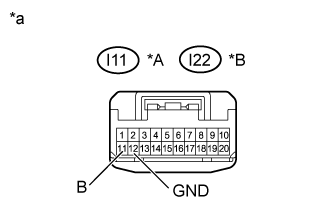
Disconnect the I11*1 or I22*2 multiplex network master switch connector.
- *1: for LHD
- *2: for RHD
Measure the resistance according to the value(s) in the tables below.
- Standard Resistance:
for LHDTester Connection
| Condition
| Specified Condition
|
A-16 (LIN2) - I11-17 (LIN1)
| Always
| Below 1 Ω
|
A-16 (LIN2) or I11-17 (LIN1) - Body ground
| Always
| 10 kΩ or higher
|
for RHDTester Connection
| Condition
| Specified Condition
|
A-16 (LIN2) - I22-17 (LIN1)
| Always
| Below 1 Ω
|
A-16 (LIN2) or I22-17 (LIN1) - Body ground
| Always
| 10 kΩ or higher
|
| 4.CHECK HARNESS AND CONNECTOR (MULTIPLEX NETWORK MASTER
SWITCH ASSEMBLY BATTERY AND BODY GROUND |
Disconnect the I11*1 or I22*2 multiplex network master switch connector.
- *1: for LHD
- *2: for RHD
Measure the resistance and voltage according to the value(s) in the tables below.
- Standard Resistance:
for LHDTester Connection
| Condition
| Specified Condition
|
I11-12 (GND) - Body ground
| Always
| Below 1 Ω
|
for RHDTester Connection
| Condition
| Specified Condition
|
I22-12 (GND) - Body ground
| Always
| Below 1 Ω
|
- Standard Voltage:
for LHDTester Connection
| Condition
| Specified Condition
|
I11-11 (B) - Body ground
| Always
| 11 to 14 V
|
for RHDTester Connection
| Condition
| Specified Condition
|
I22-11 (B) - Body ground
| Always
| 11 to 14 V
|
Text in Illustration*A
| for LHD
|
*B
| for RHD
|
*a
| Front view of wire harness connector
(to Master Switch)
|
| | REPAIR OR REPLACE HARNESS OR CONNECTOR |
|
|
| 5.REPLACE MULTIPLEX NETWORK MASTER SWITCH ASSEMBLY |
Temporarily replace the multiplex network master switch with a new or normally functioning one (Click here).
Clear the DTC (Click here).
Recheck for DTCs (Click here).
ResultResult
| Proceed to
|
DTC B1206 is not output
| A
|
DTC B1206 is output (for LHD)
| B
|
DTC B1206 is output (for RHD)
| C
|
| | REPLACE MAIN BODY ECU (MULTIPLEX NETWORK BODY ECU) (Click here) |
|
|
| | REPLACE MAIN BODY ECU (MULTIPLEX NETWORK BODY ECU) (Click here) |
|
|
| A |
|
|
|
| END (MULTIPLEX NETWORK MASTER SWITCH ASSEMBLY IS DEFECTIVE) |
|
| 7.CHECK HARNESS AND CONNECTOR (COWL SIDE JUNCTION BLOCK LH - MULTIPLEX NETWORK MASTER SWITCH ASSEMBLY) |
Disconnect the 2J cowl side junction block LH connector.
Disconnect the I11*1 or I22*2 multiplex network master switch connector.
- *1: for LHD
- *2: for RHD
Measure the resistance according to the value(s) in the tables below.
- Standard Resistance:
for LHDTester Connection
| Condition
| Specified Condition
|
2J-13 - I11-17 (LIN1)
| Always
| Below 1 Ω
|
2J-13 or I11-17 (LIN1) - Body ground
| Always
| 10 kΩ or higher
|
for RHDTester Connection
| Condition
| Specified Condition
|
2J-13 - I22-17 (LIN1)
| Always
| Below 1 Ω
|
2J-13 or I22-17 (LIN1) - Body ground
| Always
| 10 kΩ or higher
|
ResultResult
| Proceed to
|
OK (for LHD)
| A
|
OK (for RHD)
| B
|
NG
| C
|
| |
|
| | REPAIR OR REPLACE HARNESS OR CONNECTOR |
|
|