Lin Communication System -- Terminals Of Ecu |
| CHECK MAIN BODY ECU (MULTIPLEX NETWORK BODY ECU), COWL SIDE JUNCTION BLOCK LH |
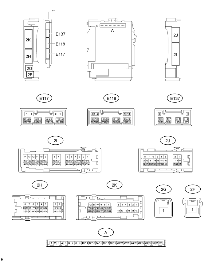
| *1 | Main Body ECU (Multiplex Network Body ECU) | - | - |
Remove the main body ECU (multiplex network body ECU) from the cowl side junction block LH.
- for LHD: Click here
- for RHD: Click here
- for LHD: Click here
Reconnect the cowl side junction block LH connectors.
Measure the resistance and voltage according to the value(s) in the table below.
Terminal No. (Symbol) Wiring Color Terminal Description Condition Specified Condition A-31 (BECU) - Body ground - Battery power supply Always Below 1 Ω A-11 (GND1) - Body ground - Ground Always Below 1 Ω A-32 (IG) - Body ground - Ignition power supply (IG signal) Ignition switch ON → Off 11 to 14 V → Below 1 V A-30 (ACC) - Body ground - ACC power supply Ignition switch ACC → Off 11 to 14 V → Below 1 V
| CHECK MULTIPLEX NETWORK MASTER SWITCH ASSEMBLY (for Models with Jam Protection Function on 4 Windows) |

Disconnect the I11*1 or I22*2 multiplex network master switch connector.
Measure the resistance and voltage according to the value(s) in the table below.
- HINT:
- *1: for LHD
- *2: for RHD
for LHD Terminal No. (Symbol) Wiring Color Terminal Description Condition Specified Condition I11-11 (B) - I11-12 (GND) R - W-B Ignition power supply Ignition switch off Below 1 Ω I11-11 (B) - I11-12 (GND) R - W-B Ignition power supply Ignition switch ON 11 to 14 V I11-12 (GND) - Body ground W-B - Body ground Ground Always Below 1 Ω for RHD Terminal No. (Symbol) Wiring Color Terminal Description Condition Specified Condition I22-11 (B) - I22-12 (GND) R - W-B Ignition power supply Ignition switch off Below 1 Ω I22-11 (B) - I22-12 (GND) R - W-B Ignition power supply Ignition switch ON 11 to 14 V I22-12 (GND) - Body ground W-B - Body ground Ground Always Below 1 Ω
| CHECK FRONT POWER WINDOW REGULATOR MOTOR ASSEMBLY LH (for Models with Jam Protection Function on 4 Windows) |

Disconnect the I12 motor connector.
Measure the resistance and voltage according to the value(s) in the table below.
Terminal No. (Symbol) Wiring Color Terminal Description Condition Specified Condition I12-2 (B) - I12-1 (GND) L - W-B Battery power supply Always 11 to 14 V I12-1 (GND) - Body ground W-B - Body ground Ground Always Below 1 Ω
| CHECK FRONT POWER WINDOW REGULATOR MOTOR ASSEMBLY RH (for Models with Jam Protection Function on 4 Windows) |

Disconnect the I4 motor connector.
Measure the resistance and voltage according to the value(s) in the table below.
Terminal No. (Symbol) Wiring Color Terminal Description Condition Specified Condition I4-2 (B) - I4-1 (GND) L - W-B Battery power supply Always 11 to 14 V I4-1 (GND) - Body ground W-B - Body ground Ground Always Below 1 Ω
| CHECK REAR POWER WINDOW REGULATOR MOTOR ASSEMBLY LH (for Models with Jam Protection Function on 4 Windows) |

Disconnect the J11 motor connector.
Measure the resistance and voltage according to the value(s) in the table below.
Terminal No. (Symbol) Wiring Color Terminal Description Condition Specified Condition J11-2 (B) - J11-1 (GND) L - W-B Battery power supply Always 11 to 14 V J11-1 (GND) - Body ground W-B - Body ground Ground Always Below 1 Ω
| CHECK REAR POWER WINDOW REGULATOR MOTOR ASSEMBLY RH (for Models with Jam Protection Function on 4 Windows) |

Disconnect the J4 motor connector.
Measure the resistance and voltage according to the value(s) in the table below.
Terminal No. (Symbol) Wiring Color Terminal Description Condition Specified Condition J4-2 (B) - J4-1 (GND) L - W-B Battery power supply Always 11 to 14 V J4-1 (GND) - Body ground W-B - Body ground Ground Always Below 1 Ω
| CHECK SLIDING ROOF DRIVE GEAR SUB-ASSEMBLY (SLIDING ROOF ECU) (w/ Sliding Roof System) |
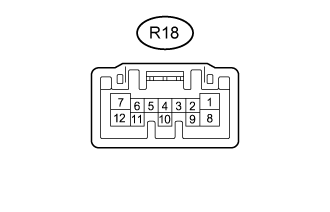 |
Disconnect the R18 ECU connector.
Measure the resistance and voltage according to the value(s) in the table below.
Terminal No. (Symbol) Wiring Color Terminal Description Condition Specified Condition R18-1 (B) - R18-12 (E) LA-L - W-B Battery power supply Always 11 to 14 V R18-12 (E) - Body ground W-B - Body ground Ground Always Below 1 Ω
| CHECK CERTIFICATION ECU (SMART KEY ECU ASSEMBLY) (w/ Entry and Start System) |
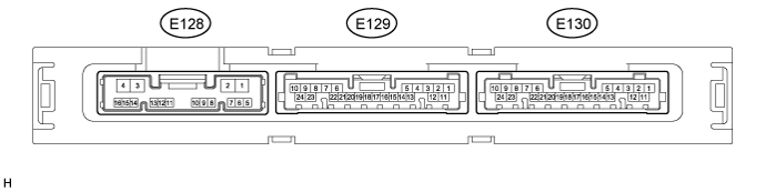
Disconnect the E130 ECU connector.
Measure the resistance and voltage according to the value(s) in the table below.
Terminal No. (Symbol) Wiring Color Terminal Description Condition Specified Condition E130-10 (+B) - E130-11 (E) P - BR Battery power supply Always 11 to 14 V E130-11 (E) - Body ground BR - Body ground Ground Always Below 1 Ω
| CHECK ID CODE BOX (IMMOBILISER CODE ECU) (w/ Entry and Start System) |
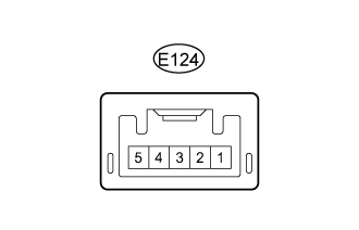 |
Disconnect the E124 ECU connector.
Measure the resistance and voltage according to the value(s) in the table below.
Terminal No. (Symbol) Wiring Color Terminal Description Condition Specified Condition E124-1 (+B) - E124-5 (GND) W - BR Battery power supply Always 11 to 14 V E124-5 (GND) - Body ground BR - Body ground Ground Always Below 1 Ω
| CHECK STEERING LOCK ACTUATOR ASSEMBLY (STEERING LOCK ECU) |

Disconnect the E26 ECU connector.
Measure the resistance and voltage according to the value(s) in the table below.
Terminal No. (Symbol) Wiring Color Terminal Description Condition Specified Condition E26-7 (B) - E26-1 (GND) G - W-B Battery power supply Always 11 to 14 V E26-1 (GND) - Body ground W-B - Body ground Ground Always Below 1 Ω
| CHECK AIR CONDITIONING AMPLIFIER (w/ Rear Heater) |

Disconnect the E36 amplifier connector.
Measure the resistance and voltage according to the value(s) in the table below.
Terminal No. (Symbol) Wiring Color Terminal Description Condition Specified Condition E36-5 (IG+) - E36-1 (GND) G - BR IG power supply Ignition switch off Below 1 V E36-5 (IG+) - E36-1 (GND) G - BR IG power supply Ignition switch ON 11 to 14 V E36-6 (+B1) - E36-1 (GND) LG - BR Battery power supply Always 11 to 14 V E36-7 (+B2) - E36-1 (GND) LG - BR Battery power supply Always 11 to 14 V E36-1 (GND) - Body ground BR - Body ground Ground Always Below 1 Ω
| CHECK AIR CONDITIONING AMPLIFIER (w/o Rear Heater) |
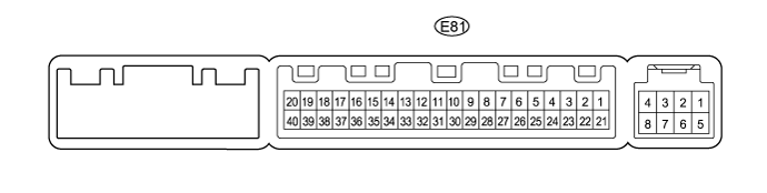
Disconnect the E81 amplifier connector.
Measure the resistance and voltage according to the value(s) in the table below.
Terminal No. (Symbol) Wiring Color Terminal Description Condition Specified Condition E81-21 (+B1) - E81-14 (GND) LG - BR Battery power supply Always 11 to 14 V E81-1 (IG+) - E81-14 (GND) G - BR IG power supply Ignition switch ON 11 to 14 V E81-1 (IG+) - E81-14 (GND) G - BR IG power supply Ignition switch off Below 1 V E81-14 (GND) - Body ground BR - Body ground Ground Always Below 1 Ω
| CHECK AIR CONDITIONING CONTROL ASSEMBLY (w/o Entry and Start System) |

Disconnect the F10 panel connector.
Measure the resistance and voltage according to the value(s) in the table below.
Terminal No. (Symbol) Wiring Color Terminal Description Condition Specified Condition F10-7 (IG+) - F10-1 (GND) B - W-B IG power supply Ignition switch ON 11 to 14 V F10-7 (IG+) - F10-1 (GND) B - W-B IG power supply Ignition switch off Below 1 V F10-1 (GND) - Body ground W-B - Body ground Ground Always Below 1 Ω
| CHECK AIR CONDITIONING CONTROL ASSEMBLY (w/ Entry and Start System) |
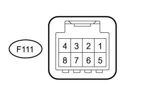 |
Disconnect the F111 panel connector.
Measure the resistance and voltage according to the value(s) in the table below.
Terminal No. (Symbol) Wiring Color Terminal Description Condition Specified Condition F111-5 (IG+) - F111-8 (GND) B - W-B IG power supply Ignition switch ON 11 to 14 V F111-5 (IG+) - F111-8 (GND) B - W-B IG power supply Ignition switch off Below 1 V F111-8 (GND) - Body ground W-B - Body ground Ground Always Below 1 Ω
| CHECK NO. 2 AIR CONDITIONING CONTROL ASSEMBLY (w/ Rear Heater) |

Disconnect the E55 panel connector.
Measure the resistance and voltage according to the value(s) in the table below.
Terminal No. (Symbol) Wiring Color Terminal Description Condition Specified Condition E55-6 (IG) - E55-1 (E) B - W-B IG power supply Ignition switch ON 11 to 14 V E55-6 (IG) - E55-1 (E) B - W-B IG power supply Ignition switch off Below 1 V E55-1 (E) - Body ground W-B - Body ground Ground Always Below 1 Ω
| CHECK RAIN SENSOR (w/ Rain Sensor) |

Disconnect the R11 rain sensor connector.
Measure the voltage according to the value(s) in the table below.
Terminal No. (Symbol) Wiring Color Terminal Description Condition Specified Condition R11-4 (SIG) - Body ground V - Body ground IG power supply Ignition switch off Below 1 V R11-4 (SIG) - Body ground V - Body ground IG power supply Ignition switch ON 11 to 14 V R11-2 (ES) - Body ground W - Body ground Ground circuit Always Below 1 V
| CHECK WINDSHIELD WIPER ECU (w/ Rain Sensor) |

Disconnect the E147 ECU connector.
Measure the voltage and resistance according to the value(s) in the table below.
Terminal No. (Symbol) Wiring Color Terminal Description Condition Specified Condition E147-2 (IG) - E147-12 (E) B - W-B IG power supply Ignition switch off Below 1 V E147-2 (IG) - E147-12 (E) B - W-B IG power supply Ignition switch ON 11 to 14 V E147-12 (E) - Body ground W-B - Body ground Ground circuit Always Below 1 Ω