Front And Side Monitor Main Switch -- Removal |
- HINT:
- Use the same procedure for RHD and LHD vehicles.
- The procedure listed below is for LHD vehicles.
| 1. DISABLE AUTO TILT AWAY FUNCTION |
Disable the function by changing the customize parameter (Click here).
- NOTICE:
- Record the current customize parameter setting (whether the Autoaway/Return function is enabled or disabled) in order to restore the current setting after finishing the operation.
- HINT:
- Performing the above operation causes the Autoaway/Return function to be disabled when the engine switch is turned off.
Turn the engine switch on (IG). Operate the tilt and telescopic switch to fully extend and lower the steering column assembly.
Turn the engine switch off.
| 2. DISCONNECT CABLE FROM NEGATIVE BATTERY TERMINAL |
- CAUTION:
- Wait at least 90 seconds after disconnecting the cable from the negative (-) battery terminal to disable the SRS system.
- NOTICE:
- When disconnecting the cable, some systems need to be initialized after the cable is reconnected (Click here).
| 3. REMOVE INSTRUMENT SIDE PANEL LH |
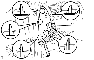 |
Place protective tape as shown in the illustration.
Text in Illustration *1 Protective Tape
Using a moulding remover, detach the 6 claws and remove the instrument side panel.
| 4. REMOVE NO. 1 INSTRUMENT CLUSTER FINISH PANEL GARNISH |
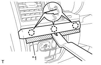 |
Place protective tape as shown in the illustration.
Text in Illustration *1 Protective Tape
Using a moulding remover, detach the 3 claws and remove the No. 1 instrument cluster finish panel garnish.
| 5. REMOVE NO. 2 INSTRUMENT PANEL FINISH PANEL CUSHION |
 |
Put protective tape around the No. 2 instrument panel finish panel cushion.
Text in Illustration *1 Protective Tape
Using a moulding remover, detach the 7 claws and remove the No. 2 instrument panel finish panel cushion.
| 6. REMOVE LOWER INSTRUMENT PANEL PAD SUB-ASSEMBLY LH |
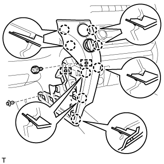 |
Remove the clip and screw.
Detach the 8 claws.
Disconnect the connectors, detach the 2 clamps and remove the lower instrument panel pad sub-assembly.
| 7. REMOVE NO. 2 INSTRUMENT CLUSTER FINISH PANEL GARNISH |
Place protective tape as shown in the illustration.
Using a moulding remover, detach the 2 claws and remove the No. 2 instrument cluster finish panel garnish.
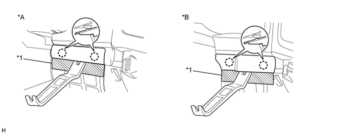
Text in Illustration *A w/ Entry and Start System *B w/o Entry and Start System *1 Protective Tape - -
| 8. REMOVE INSTRUMENT CLUSTER FINISH PANEL SUB-ASSEMBLY |
Detach the 4 claws.
 |
Detach the 9 claws.
 |
w/ Multi-information Display:
Remove the finish panel and disconnect the 2 connectors.
w/o Multi-information Display:
Remove the finish panel and disconnect the connector.
| 9. REMOVE MAIN SWITCH ASSEMBLY |
Detach the 2 claws and remove the main switch assembly.
Text in Illustration *A for LHD *B for RHD
 |