Rear View Monitor System Image From Camera For Rear View Monitor Is Abnormal
DESCRIPTION
WIRING DIAGRAM
INSPECTION PROCEDURE
CHECK HARNESS AND CONNECTOR (RADIO AND DISPLAY RECEIVER ASSEMBLY - REAR TELEVISION CAMERA ASSEMBLY)
CHECK RADIO AND DISPLAY RECEIVER ASSEMBLY (CA+, CGND)
CHECK REAR TELEVISION CAMERA ASSEMBLY (CV+, CGND)
CHECK RADIO AND DISPLAY RECEIVER ASSEMBLY
REAR VIEW MONITOR SYSTEM - Image from Camera for Rear View Monitor is Abnormal |
DESCRIPTION
The display signal of the rear television camera assembly is transmitted to the radio and display receiver assembly.
WIRING DIAGRAM
INSPECTION PROCEDURE
- NOTICE:
- When replacing the radio and display receiver assembly, it is necessary perform the vehicle contract setting for Connected Service (Click here).
| 1.CHECK HARNESS AND CONNECTOR (RADIO AND DISPLAY RECEIVER ASSEMBLY - REAR TELEVISION CAMERA ASSEMBLY) |
Disconnect the F118 radio and display receiver assembly connector.
Disconnect the S31 rear television camera assembly connector.
Measure the resistance according to the value(s) in the table below.
- Standard Resistance:
Tester Connection
| Condition
| Specified Condition
|
F118-12 (V+) - S31-3 (CV+)
| Always
| Below 1 Ω
|
F118-24 (V-) - S31-2 (CV-)
| Always
| Below 1 Ω
|
F118-11 (CA+) - S31-6 (CB+)
| Always
| Below 1 Ω
|
F118-23 (CGND) - S31-5 (CGND)
| Always
| Below 1 Ω
|
F118-12 (V+) or S31-3 (CV+) - Body ground
| Always
| 10 kΩ or higher
|
F118-24 (V-) or S31-2 (CV-) - Body ground
| Always
| 10 kΩ or higher
|
F118-11 (CA+) or S31-6 (CB+) - Body ground
| Always
| 10 kΩ or higher
|
F118-23 (CGND) or S31-5 (CGND) - Body ground
| Always
| 10 kΩ or higher
|
| | REPAIR OR REPLACE HARNESS OR CONNECTOR |
|
|
| 2.CHECK RADIO AND DISPLAY RECEIVER ASSEMBLY (CA+, CGND) |
Remove the radio and display receiver assembly with the connector connected (Click here).
Measure the resistance according to the value(s) in the table below.
- Standard Resistance:
Tester Connection
| Condition
| Specified Condition
|
F118-23 (CGND) - Body ground
| Always
| Below 1 Ω
|
F118-24 (V-) - Body ground
| Always
| Below 1 Ω
|
Measure the voltage according to the value(s) in the table below.
- Standard Voltage:
Tester Connection
| Switch Condition
| Specified Condition
|
F118-11 (CA+) - Body ground
| Engine switch on (ACC)
| 5.5 to 7.05 V
|
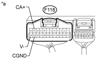
Text in Illustration*a
| Component with harness connected
(Radio and Display Receiver Assembly)
|
| | REPLACE RADIO AND DISPLAY RECEIVER ASSEMBLY (Click here) |
|
|
| 3.CHECK REAR TELEVISION CAMERA ASSEMBLY (CV+, CGND) |
Remove the radio and display receiver assembly with the connector connected (Click here).
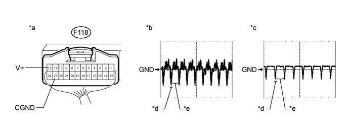
Text in Illustration*a
| Component with harness connected
(Radio and Display Receiver Assembly)
| *b
| Waveform 1
|
*c
| Waveform 2
| *d
| Synchronization Signal
|
*e
| Video Waveform
| -
| -
|
Check the waveform of the rear television camera assembly using an oscilloscope.
- HINT:
- A waterproof connector is used for the rear television camera assembly. Therefore, inspect the waveform at the radio and display receiver assembly with the connector connected.
- The video waveform changes according to the image sent by the rear television camera assembly.
Measurement ConditionItem
| Content
|
Tester No. (Symbol)
| F118-12 (V+) - F118-23 (CGND)
|
Tool Setting
| 0.2 V/DIV., 50 μS/DIV
|
Condition
| Waveform 1: Engine switch on (IG), shift lever in R, camera lens is not covered, displaying an image
Waveform 2: Engine switch on (IG), shift lever in R, camera lens is covered, blacking out the screen
|
- OK:
- Waveform is as shown in the illustration.
| | REPLACE REAR TELEVISION CAMERA ASSEMBLY (Click here) |
|
|
| 4.CHECK RADIO AND DISPLAY RECEIVER ASSEMBLY |
Replace the radio and display receiver assembly with a new or normally functioning one (Click here).
Check the operation of rear view monitor system.
- OK:
- Rear view monitor system is operated normally.
| | REPLACE REAR TELEVISION CAMERA ASSEMBLY (Click here) |
|
|
| OK |
|
|
|
| END (RADIO AND DISPLAY RECEIVER ASSEMBLY IS DEFECTIVE) |
|