Dtc B1575 Gvif Disconnected (From Emv/Mm Integrated Device To Multi Display)
DESCRIPTION
WIRING DIAGRAM
INSPECTION PROCEDURE
CLEAR DTC
CHECK DTC
CHECK HARNESS AND CONNECTOR (GVIF CABLE)
CHECK HARNESS AND CONNECTOR (GVIF CABLE)
DTC B1575 GVIF Disconnected (from EMV/MM Integrated Device to Multi Display) |
DESCRIPTION
DTC Code
| DTC Detection Condition
| Trouble Area
|
B1575
| GVIF disconnected (from Multi-media module receiver assembly to multi-display assembly)
| - Harness or connector (GVIF cable)
- Multi-media module receiver assembly
|
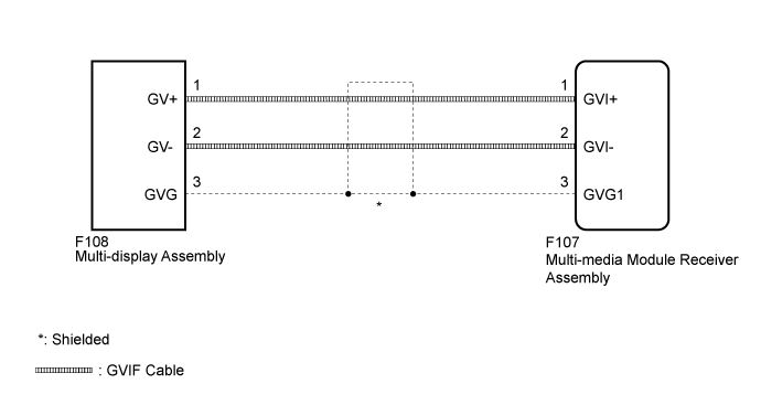
WIRING DIAGRAM
INSPECTION PROCEDURE
- NOTICE:
- Depending on the parts that are replaced during vehicle inspection or maintenance, performing initialization, registration or calibration may be needed. Refer to Precaution for Navigation System (Click here).
Clear the DTCs (Click here).
Recheck for DTCs and check if the same DTC is output again (Click here).
- OK:
- No DTCs are output.
| 3.CHECK HARNESS AND CONNECTOR (GVIF CABLE) |
Check that the digital signal lines between the multi-display assembly and multi-media module receiver assembly are not sharply bent or pinched, and that the connectors are properly connected and there are no other installation problems.
- OK:
- There are no installation problems.
| | REPLACE HARNESS AND CONNECTOR (GVIF CABLE) |
|
|
| 4.CHECK HARNESS AND CONNECTOR (GVIF CABLE) |
Disconnect the F108 multi-display assembly connector.
Disconnect the F107 multi-media module receiver assembly connector.
Measure the resistance according to the value(s) in the table below.
- Standard Resistance:
Tester Connection
| Condition
| Specified Condition
|
F108-1 (GV+) - F107-1 (GVI+)
| Always
| Below 1 Ω
|
F108-2 (GV-) - F107-2 (GVI-)
| Always
| Below 1 Ω
|
F108-3 (GVG) - F107-3 (GVG1)
| Always
| Below 1 Ω
|
F108-1 (GV+) - Body ground
| Always
| 10 kΩ or higher
|
F108-2 (GV-) - Body ground
| Always
| 10 kΩ or higher
|
F108-3 (GVG) - Body ground
| Always
| 10 kΩ or higher
|
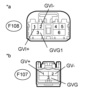
Text in Illustration*a
| Front view or wire harness connector
(to Multi-media Module Receiver Assembly)
|
*b
| Front view or wire harness connector
(to Multi-display Assembly)
|
| | REPLACE HARNESS AND CONNECTOR (GVIF CABLE) |
|
|
| OK |
|
|
|
| REPLACE MULTI-MEDIA MODULE RECEIVER ASSEMBLY (Click here) |
|