Land Cruiser URJ200 URJ202 GRJ200 VDJ200 - 1VD-FTV ENGINE CONTROL
CHECK OTHER DTC OUTPUT (IN ADDITION TO DTC P2564 P2565, P2588 OR P2589)
CHECK HARNESS AND CONNECTOR (ECM - NOZZLE VANE POSITION SENSOR)
REPLACE TURBOCHARGER SUB-ASSEMBLY (NOZZLE VANE POSITION SENSOR)
REPAIR OR REPLACE HARNESS OR CONNECTOR
CONFIRM WHETHER MALFUNCTION HAS BEEN SUCCESSFULLY REPAIRED
DTC P2564 Turbocharger/Supercharger Boost Control Position Sensor "A" Circuit Low
DTC P2565 Turbocharger/Supercharger Boost Control Position Sensor "A" Circuit High
DTC P2588 Turbocharger/Supercharger Boost Control Position Sensor "B" Circuit Low
DTC P2589 Turbocharger/Supercharger Boost Control Position Sensor "B" Circuit High
DESCRIPTION
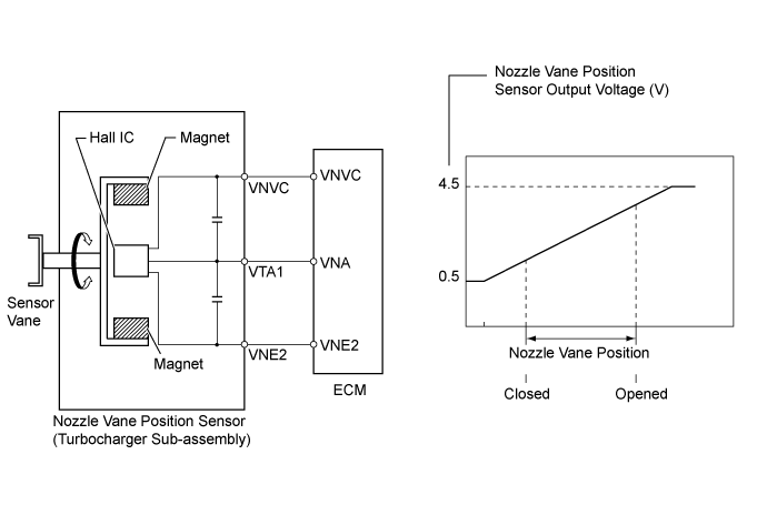
The variable nozzle vane type turbocharger consists primarily of a compressor wheel, turbine wheel, nozzle vane, unison ring, DC motor and nozzle vane position sensor.
The nozzle vane position sensor consists of a Hall IC and a magnetic yoke that rotates in unison with the movement of the linkage that actuates the nozzle vane. The nozzle vane position sensor converts the changes in the magnetic flux that are caused by the rotation of the DC motor (hence, the rotation of the magnetic yoke) into electric signals, and outputs them to the ECM. The ECM determines the actual nozzle vane position from the electric signals in order to calculate the target nozzle vane position.
| DTC Detection Drive Pattern | DTC Detection Condition | Trouble Area |
| Engine switch on (IG) for 1 second | VNA or VNA2 voltage is 0.1 V or less for 2.1 seconds (1 trip detection logic). | Nozzle vane position sensor (turbocharger sub-assembly) Open or short in nozzle vane position sensor circuit ECM |
| DTC Detection Drive Pattern | DTC Detection Condition | Trouble Area |
| Engine switch on (IG) for 1 second | VNA or VNA2 voltage is 4.9 V or higher for 2.1 seconds (1 trip detection logic). | Nozzle vane position sensor (turbocharger sub-assembly) Open or short in nozzle vane position sensor circuit ECM |
- HINT:
- If DTC P2564, P2565, P2588 and/or P2589 is stored due to the nozzle vane being stuck open, the following symptoms may appear:
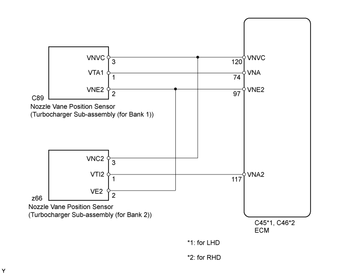
WIRING DIAGRAM
INSPECTION PROCEDURE
- NOTICE:
- HINT:
- Read freeze frame data using the GTS. Freeze frame data records the engine condition when malfunctions are detected. When troubleshooting, freeze frame data can help determine if the vehicle was moving or stationary, if the engine was warmed up or not, and other data from the time the malfunction occurred.
| 1.CHECK OTHER DTC OUTPUT (IN ADDITION TO DTC P2564 P2565, P2588 OR P2589) |
Connect the GTS to the DLC3.
Turn the engine switch on (IG) and turn the GTS on.
Enter the following menus: Engine and ECT / Trouble Codes.
Read the DTCs.
| Result | Proceed to |
| P2564 P2565, P2588 or P2589 is output | A |
| P2564 P2565, P2588 or P2589 and other DTCs are output | B |
|
| ||||
| A | |
| 2.CHECK HARNESS AND CONNECTOR (ECM - NOZZLE VANE POSITION SENSOR) |
Disconnect the nozzle vane position sensor connector.
Disconnect the ECM.
Measure the resistance according to the value(s) in the table below.
- Standard Resistance:
for LHD Tester Connection Condition Specified Condition C89-3 (VNVC) - C45-120 (VNVC) Always Below 1 Ω C89-2 (VNE2) - C45-97 (VNE2) Always Below 1 Ω C89-1 (VTA1) - C45-74 (VNA) Always Below 1 Ω z66-3 (VNC2) - C45-120 (VNVC) Always Below 1 Ω z66-2 (VE2) - C45-97 (VNE2) Always Below 1 Ω z66-1 (VTI2) - C45-117 (VNA2) Always Below 1 Ω C89-3 (VNVC) or C45-120 (VNVC) - Body ground Always 10 kΩ or higher C89-1 (VTA1) or C45-74 (VNA) - Body ground Always 10 kΩ or higher z66-3 (VNC2) or C45-120 (VNVC) - Body ground Always 10 kΩ or higher z66-1 (VTI2) or C45-117 (VNA2) - Body ground Always 10 kΩ or higher
- Standard Resistance:
for RHD Tester Connection Condition Specified Condition C89-3 (VNVC) - C46-120 (VNVC) Always Below 1 Ω C89-2 (VNE2) - C46-97 (VNE2) Always Below 1 Ω C89-1 (VTA1) - C46-74 (VNA) Always Below 1 Ω z66-3 (VNC2) - C46-120 (VNVC) Always Below 1 Ω z66-2 (VE2) - C46-97 (VNE2) Always Below 1 Ω z66-1 (VTI2) - C46-117 (VNA2) Always Below 1 Ω C89-3 (VNVC) or C46-120 (VNVC) - Body ground Always 10 kΩ or higher C89-1 (VTA1) or C46-74 (VNA) - Body ground Always 10 kΩ or higher z66-3 (VNC2) or C46-120 (VNVC) - Body ground Always 10 kΩ or higher z66-1 (VTI2) or C46-117 (VNA2) - Body ground Always 10 kΩ or higher
Reconnect the nozzle vane position sensor connector.
Reconnect the ECM connector.
|
| ||||
| OK | |
| 3.INSPECT ECM (VNVC VOLTAGE) |
Disconnect the nozzle vane position sensor connector.
Measure the voltage according to the value(s) in the table below.
- Standard Voltage:
Tester Connection Switch Condition Specified Condition C89-3 (VNVC) - C89-2 (VNE2) Engine switch on (IG) 4.5 to 5.5 V z66-3 (VNC2) - z66-2 (VE2) Engine switch on (IG) 4.5 to 5.5 V
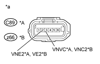
| *A | for Bank 1 |
| *B | for Bank 2 |
| *a | Front view of wire harness connector (to Nozzle Vane Position Sensor) |
|
| ||||
| OK | |
| 4.REPLACE TURBOCHARGER SUB-ASSEMBLY (NOZZLE VANE POSITION SENSOR) |
When DTC P2564 or P2565 is output:
When DTC P2588 or P2589 is output:
|
| ||||
| 5.REPLACE ECM |
Replace the ECM ().
|
| ||||
| 6.REPAIR OR REPLACE HARNESS OR CONNECTOR |
Repair or replace the harness or connector.
| NEXT | |
| 7.CONFIRM WHETHER MALFUNCTION HAS BEEN SUCCESSFULLY REPAIRED |
Connect the GTS to the DLC3.
Clear the DTCs ().
Turn the engine switch off and leave the vehicle for 15 seconds.
Turn the engine switch on (IG) for 1 second.
Confirm that the DTC is not output again.
- HINT:
- Perform the following procedure using the GTS to determine whether or not the DTC judgment has been carried out.
Enter the following menus: Engine and ECT / Utility / All Readiness.
Input DTC P2564 P2565, P2588 or P2589.
Check that STATUS is NORMAL. If STATUS is INCOMPLETE or N/A, idle the engine.
| NEXT | ||
| ||