Dtc B15D5 Rear Seat Entertainment System Disconnected
DESCRIPTION
WIRING DIAGRAM
INSPECTION PROCEDURE
CLEAR DTC
CHECK FOR DTC
CHECK HARNESS AND CONNECTOR (MULTI-DISPLAY CONTROLLER SUB-ASSEMBLY - BATTERY AND BODY GROUND)
CHECK HARNESS AND CONNECTOR (MULTI-MEDIA MODULE RECEIVER ASSEMBLY - MULTI-DISPLAY CONTROLLER SUB-ASSEMBLY)
CHECK MULTI-DISPLAY CONTROLLER SUB-ASSEMBLY
CLEAR DTC
CHECK FOR DTC
DTC B15D5 Rear Seat Entertainment System Disconnected |
DESCRIPTION
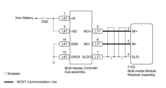
The multi-media module receiver assembly and multi-display controller sub-assembly are connected by a MOST communication line.When a MOST communication error occurs between the multi-media module receiver assembly and multi-display controller sub-assembly, these DTCs will be stored.DTC Code
| DTC Detection Condition
| Trouble Area
|
B15D5*
| A device that is listed in the MOST network connected device record of the master unit is missing.
| - MOST communication line
- Multi-media module receiver assembly
- Multi-display controller sub-assembly
- Harness or connector
|
- HINT:
- *: Even if no fault is present, this DTC may be stored depending on the battery condition or engine start voltage.
- The multi-media module receiver assembly is the master unit.
WIRING DIAGRAM
INSPECTION PROCEDURE
- NOTICE:
- Inspect the fuses for circuits related to this system before performing the following inspection procedure.
Clear the DTCs (Click here).
Recheck for DTCs and check if the same DTC is output again (Click here).
- OK:
- No DTCs are output.
| 3.CHECK HARNESS AND CONNECTOR (MULTI-DISPLAY CONTROLLER SUB-ASSEMBLY - BATTERY AND BODY GROUND) |
Disconnect the multi-display controller sub-assembly connector.
Measure the resistance according to the value(s) in the table below.
- Standard Resistance:
Tester Connection
| Condition
| Specified Condition
|
L67-14 (GND) - Body ground
| Always
| Below 1 Ω
|
L67-15 (GND5) - Body ground
| Always
| Below 1 Ω
|
Measure the voltage according to the value(s) in the table below.
- Standard Voltage:
Tester Connection
| Condition
| Specified Condition
|
L67-1 (+B) - Body ground
| Always
| 11 to 14 V
|
L67-6 (+B2) - Body ground
| Always
| 11 to 14 V
|
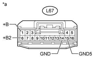
Text in Illustration*a
| Front view of wire harness connector
(to Multi-display Controller Sub-assembly)
|
| | REPAIR OR REPLACE HARNESS OR CONNECTOR |
|
|
| 4.CHECK HARNESS AND CONNECTOR (MULTI-MEDIA MODULE RECEIVER ASSEMBLY - MULTI-DISPLAY CONTROLLER SUB-ASSEMBLY) |
Disconnect the F102 multi-media module receiver assembly connector.
Disconnect the L77 multi-display controller sub-assembly connector.
Measure the resistance according to the value(s) in the table below.
- Standard Resistance:
Tester Connection
| Condition
| Specified Condition
|
F102-2 (MI+) - L77-5 (MO+)
| Always
| Below 1 Ω
|
F102-3 (MI-) - L77-6 (MO-)
| Always
| Below 1 Ω
|
F102-4 (SLDI) - L77-7 (SLDO)
| Always
| Below 1 Ω
|
F102-2 (MI+) or L77-5 (MO+) - Body ground
| Always
| 10 kΩ or higher
|
F102-3 (MI-) or L77-6 (MO-) - Body ground
| Always
| 10 kΩ or higher
|
F102-4 (SLDI) or L77-7 (SLDO) - Body ground
| Always
| 10 kΩ or higher
|
| | REPAIR OR REPLACE HARNESS OR CONNECTOR |
|
|
| 5.CHECK MULTI-DISPLAY CONTROLLER SUB-ASSEMBLY |
Replace the multi-display controller sub-assembly with a new or known good one (Click here).
Clear the DTCs (Click here).
Recheck for DTCs and check if the same DTC is output again (Click here).
- OK:
- No DTCs are output.
| | REPLACE MULTI-MEDIA MODULE RECEIVER ASSEMBLY (Click here) |
|
|
| OK |
|
|
|
| END (MULTI-DISPLAY CONTROLLER SUB-ASSEMBLY IS DEFECTIVE) |
|