Land Cruiser URJ200 URJ202 GRJ200 VDJ200 - 1VD-FTV ENGINE CONTROL
READ VALUE USING GTS (FUEL TEMPERATURE)
READ VALUE USING GTS (CHECK FOR OPEN IN WIRE HARNESS)
CHECK HARNESS AND CONNECTOR (FUEL TEMPERATURE SENSOR - ECM)
CONFIRM GOOD CONNECTION TO ECM. IF OK, REPLACE ECM.
READ VALUE USING GTS (CHECK FOR SHORT IN WIRE HARNESS)
REPLACE FUEL TEMPERATURE SENSOR
CHECK HARNESS AND CONNECTOR (FUEL TEMPERATURE SENSOR - ECM)
PERFORM SUPPLY PUMP INITIALIZATION
REPAIR OR REPLACE HARNESS OR CONNECTOR
CONFIRM WHETHER MALFUNCTION HAS BEEN SUCCESSFULLY REPAIRED
DTC P0180 Fuel Temperature Sensor "A" Circuit
DTC P0182 Fuel Temperature Sensor "A" Circuit Low Input
DTC P0183 Fuel Temperature Sensor "A" Circuit High Input
DESCRIPTION
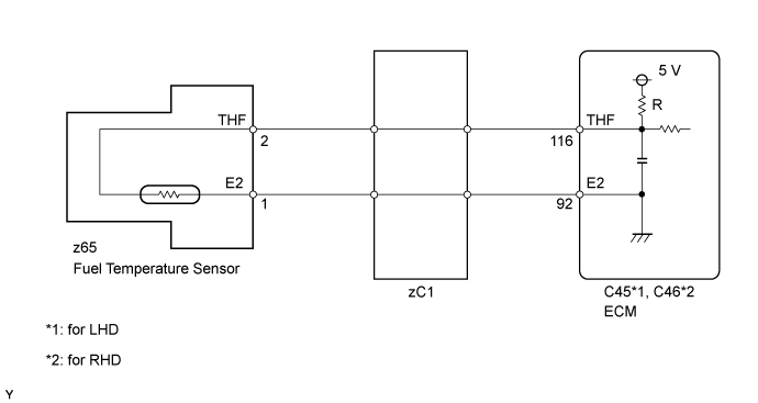
The fuel temperature sensor monitors the fuel temperature. The fuel temperature sensor has a thermistor that varies its resistance depending on the fuel temperature. When the fuel temperature is low, the resistance of the thermistor is high. When the temperature is high, the resistance is low. The variations of resistance are communicated to the ECM as changes of voltage (See Fig. 1).
The fuel temperature sensor is connected to the ECM. The 5 V power source voltage in the ECM is applied to the fuel temperature sensor from terminal THF via resistor R.
Resistor R and the fuel temperature sensor are connected in series. When the resistance value of the fuel temperature sensor changes due to a change in fuel temperature, the voltage at terminal THF also changes. Based on this signal, the ECM corrects the pressure control compensation of the fuel supply pump assembly.

| DTC Detection Drive Pattern | DTC Detection Condition | Trouble Area |
| Engine switch on (IG) for 0.5 seconds | Open or short in the fuel temperature sensor circuit for 0.5 seconds (1 trip detection logic). | Open or short in fuel temperature sensor circuit Fuel temperature sensor (fuel supply pump assembly) ECM |
| DTC Detection Drive Pattern | DTC Detection Condition | Trouble Area |
| Engine switch on (IG) for 0.5 seconds | Short in the fuel temperature sensor circuit for 0.5 seconds (1 trip detection logic). | Short in fuel temperature sensor circuit Fuel temperature sensor (fuel supply pump assembly) ECM |
| DTC Detection Drive Pattern | DTC Detection Condition | Trouble Area |
| Engine switch on (IG) for 0.5 seconds | Open in the fuel temperature sensor circuit for 0.5 seconds (1 trip detection logic). | Open in fuel temperature sensor circuit Fuel temperature sensor (fuel supply pump assembly) ECM |
| DTC No. | Data List |
| P0180 P0182 P0183 | Fuel Temp |
- HINT:
WIRING DIAGRAM
INSPECTION PROCEDURE
- NOTICE:
- HINT:
- Read freeze frame data using the GTS. Freeze frame data records the engine condition when malfunctions are detected. When troubleshooting, freeze frame data can help determine if the vehicle was moving or stationary, if the engine was warmed up or not, and other data from the time the malfunction occurred.
| 1.READ VALUE USING GTS (FUEL TEMPERATURE) |
Connect the GTS to the DLC3.
Turn the engine switch on (IG) and turn the GTS on.
Enter the following menus: Engine and ECT / Data List / Fuel Temp.
Read the value.
- OK:
- Same as the actual fuel temperature
| Result | Proceed to |
| -40°C (-40°F) | A |
| 140°C (284°F) or higher | B |
| OK (Same as actual fuel temperature) | C |
- HINT:
|
| ||||
|
| ||||
| A | |
| 2.READ VALUE USING GTS (CHECK FOR OPEN IN WIRE HARNESS) |
Disconnect the fuel temperature sensor connector.
Connect terminals 2 and 1 of the fuel temperature sensor connector.
Connect the GTS to the DLC3.
Turn the engine switch on (IG) and turn the GTS on.
Enter the following menus: Engine and ECT / Data List / Fuel Temp.
Read the value.
- OK:
- 140°C (284°F) or higher
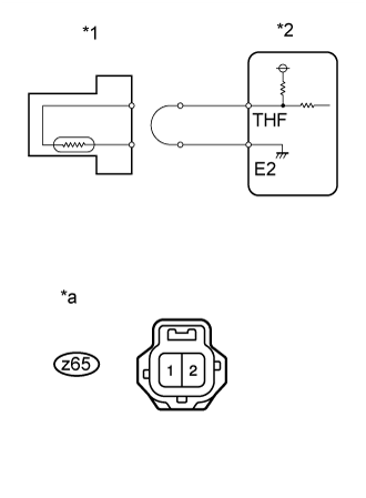
| *1 | Fuel Temperature Sensor |
| *2 | ECM |
| *a | Front view of wire harness connector (to Fuel Temperature Sensor) |
Reconnect the fuel temperature sensor connector.
|
| ||||
| NG | |
| 3.CHECK HARNESS AND CONNECTOR (FUEL TEMPERATURE SENSOR - ECM) |
Disconnect the fuel temperature sensor connector.
Disconnect the ECM connector.
Measure the resistance according to the value(s) in the table below.
- Standard Resistance:
for LHD Tester Connection Condition Specified Condition z65-2 (THF) - C45-116 (THF) Always Below 1 Ω z65-1 (E2) - C45-92 (E2) Always Below 1 Ω
- Standard Resistance:
for RHD Tester Connection Condition Specified Condition z65-2 (THF) - C46-116 (THF) Always Below 1 Ω z65-1 (E2) - C46-92 (E2) Always Below 1 Ω
Reconnect the fuel temperature sensor connector.
Reconnect the ECM connector.
|
| ||||
| OK | |
| 4.CONFIRM GOOD CONNECTION TO ECM. IF OK, REPLACE ECM. |
Replace the ECM ().
|
| ||||
| 5.READ VALUE USING GTS (CHECK FOR SHORT IN WIRE HARNESS) |
Disconnect the fuel temperature sensor connector.
Connect the GTS to the DLC3.
Turn the engine switch on (IG) and turn the GTS on.
Enter the following menus: Engine and ECT / Data List / Fuel Temp.
Read the value.
- OK:
- -40°C (-40°F)
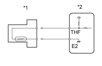
| *1 | Fuel Temperature Sensor |
| *2 | ECM |
Reconnect the fuel temperature sensor connector.
|
| ||||
| OK | |
| 6.REPLACE FUEL TEMPERATURE SENSOR |
Replace the fuel temperature sensor ().
|
| ||||
| 7.CHECK HARNESS AND CONNECTOR (FUEL TEMPERATURE SENSOR - ECM) |
Disconnect the fuel temperature sensor connector.
Disconnect the ECM connector.
Measure the resistance according to the value(s) in the table below.
- Standard Resistance:
for LHD Tester Connection Condition Specified Condition z65-2 (THF) or C45-116 (THF) - Body ground Always 10 kΩ or higher
- Standard Resistance:
for RHD Tester Connection Condition Specified Condition z65-2 (THF) or C46-116 (THF) - Body ground Always 10 kΩ or higher
Reconnect the fuel temperature sensor connector.
Reconnect the ECM connector.
|
| ||||
| OK | |
| 8.REPLACE ECM |
Replace the ECM ().
|
| ||||
| 9.BLEED AIR FROM FUEL SYSTEM |
Bleed the air from the fuel system ().
Perform PM forced regeneration ().
- HINT:
- When fuel lines are disconnected, air may enter the fuel lines, leading to engine starting trouble. Therefore, perform forced regeneration and bleed the air from the fuel lines.
| NEXT | |
| 10.PERFORM SUPPLY PUMP INITIALIZATION |
Perform supply pump initialization ().
|
| ||||
| 11.REPAIR OR REPLACE HARNESS OR CONNECTOR |
Repair or replace the harness or connector.
| NEXT | |
| 12.CONFIRM WHETHER MALFUNCTION HAS BEEN SUCCESSFULLY REPAIRED |
Connect the GTS to the DLC3.
Clear the DTCs ().
Turn the engine switch on (IG) for 1 second or more.
Enter the following menus: Engine and ECT / Trouble Codes.
Confirm that the DTC is not output again.
| NEXT | ||
| ||