Audio And Visual System (For Radio And Display Type) Microphone Circuit Between Microphone And Radio Receiver
DESCRIPTION
WIRING DIAGRAM
INSPECTION PROCEDURE
CHECK HARNESS AND CONNECTOR (RADIO AND DISPLAY RECEIVER ASSEMBLY - MAP LIGHT ASSEMBLY)
CHECK RADIO AND DISPLAY RECEIVER ASSEMBLY
CHECK TELEPHONE MICROPHONE ASSEMBLY
AUDIO AND VISUAL SYSTEM (for Radio and Display Type) - Microphone Circuit between Microphone and Radio Receiver |
DESCRIPTION
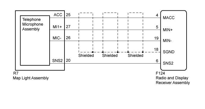
Using this circuit, the radio and display receiver assembly sends power to the telephone microphone assembly, and the telephone microphone assembly sends microphone signals to the radio and display receiver assembly.
WIRING DIAGRAM
INSPECTION PROCEDURE
| 1.CHECK HARNESS AND CONNECTOR (RADIO AND DISPLAY RECEIVER ASSEMBLY - MAP LIGHT ASSEMBLY) |
Disconnect the F124 radio and display receiver assembly connector.
Disconnect the R7 map light assembly connector.
Measure the resistance according to the value(s) in the table below.
- Standard Resistance:
Tester Connection
| Condition
| Specified Condition
|
F124-4 (MACC) - R7-25 (ACC)
| Always
| Below 1 Ω
|
F124-5 (MIN+) - R7-27 (MI1+)
| Always
| Below 1 Ω
|
F124-19 (MIN-) - R7-26 (MIC-)
| Always
| Below 1 Ω
|
F124-6 (SNS2) - R7-20 (SNS2)
| Always
| Below 1 Ω
|
F124-4 (MACC) - Body ground
| Always
| 10 kΩ or higher
|
F124-5 (MIN+) - Body ground
| Always
| 10 kΩ or higher
|
F124-19 (MIN-) - Body ground
| Always
| 10 kΩ or higher
|
F124-18 (SGND) - Body ground
| Always
| 10 kΩ or higher
|
F124-6 (SNS2) - Body ground
| Always
| 10 kΩ or higher
|
| | REPAIR OR REPLACE HARNESS OR CONNECTOR |
|
|
| 2.CHECK RADIO AND DISPLAY RECEIVER ASSEMBLY |
Remove the radio and display receiver assembly with its connectors still connected (Click here).
Measure the voltage according to the value(s) in the table below.
- Standard Voltage:
Tester Connection
| Switch Condition
| Specified Condition
|
F124-4 (MACC) - Body ground
| Engine switch on (ACC)
| 4 to 6 V
|
Measure the resistance according to the value(s) in the table below.
- Standard Resistance:
Tester Connection
| Condition
| Specified Condition
|
F124-18 (SGND) - Body ground
| Always
| Below 1 Ω
|
F124-19 (MIN-) - Body ground
| Always
| Below 1 Ω
|
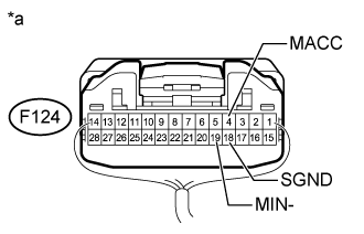
Text in Illustration*a
| Component with harness connected
(Radio and Display Receiver Assembly)
|
| | PROCEED TO NEXT SUSPECTED AREA SHOWN IN PROBLEM SYMPTOMS TABLE (Click here) |
|
|
| 3.CHECK TELEPHONE MICROPHONE ASSEMBLY |
Replace the telephone microphone assembly with a known good one (Click here).
Check that the malfunction disappears.
- OK:
- Malfunction disappears.
| OK |
|
|
|
| END (TELEPHONE MICROPHONE ASSEMBLY IS DEFECTIVE) |
|