Dtc B15C3 Speaker Output Short
DESCRIPTION
WIRING DIAGRAM
INSPECTION PROCEDURE
CLEAR DTC
CHECK FOR DTC
CHECK VEHICLE CONDITION (SPEAKER TYPE)
CHECK HARNESS AND CONNECTOR (SPEAKER CIRCUIT)
INSPECT FRONT NO. 1 SPEAKER ASSEMBLY
CHECK FRONT NO. 2 SPEAKER ASSEMBLY
INSPECT REAR SPEAKER SET
CHECK HARNESS AND CONNECTOR (SPEAKER CIRCUIT)
INSPECT FRONT NO. 1 SPEAKER ASSEMBLY
CHECK FRONT NO. 2 SPEAKER ASSEMBLY
CHECK FRONT NO. 4 SPEAKER ASSEMBLY
CHECK FRONT NO. 3 SPEAKER ASSEMBLY
INSPECT REAR SPEAKER SET
DTC B15C3 Speaker Output Short |
DESCRIPTION
DTC Code
| DTC Detection Condition
| Trouble Area
|
B15C3
| A short is detected in the speaker output circuit.
| - Radio and Display Receiver Assembly*1
- Stereo component amplifier assembly*2
- Speakers
- Harness or connector
|
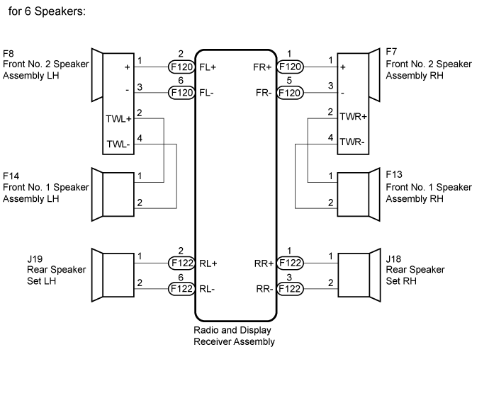
- *1: for 6 Speakers
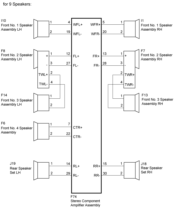
- *2: for 9 Speakers
WIRING DIAGRAM
INSPECTION PROCEDURE
- HINT:
- After the inspection is completed, clear the DTCs.
- When replacing the radio and display receiver assembly, it is necessary to perform the vehicle contract setting for Connected Services (w/ Connected Services Function).
Clear the DTC (Click here).
Recheck for DTCs and check if the same DTC is output again (Click here).
- OK:
- DTC B15C3 is not output.
| 3.CHECK VEHICLE CONDITION (SPEAKER TYPE) |
Check the vehicle condition.
ResultResult
| Proceed to
|
for 6 Speakers
| A
|
for 9 Speakers
| B
|
| 4.CHECK HARNESS AND CONNECTOR (SPEAKER CIRCUIT) |
- *1: for RH Side
- *2: for LH Side
Disconnect the F122 and F120 radio and display receiver assembly connectors.
Disconnect the F13*1 and/or F14*2 front No. 1 speaker assembly connector.
Disconnect the F7*1 and/or F8*2 front No. 2 speaker assembly connector.
Disconnect the J18*1 and/or J19*2 rear speaker set connector.
- Standard Resistance:
RH SideTester Connection
| Condition
| Specified Condition
|
F120-1 (FR+) - F7-1 (+)
| Always
| Below 1 Ω
|
F120-5 (FR-) - F7-3 (-)
| Always
| Below 1 Ω
|
F7-2 (TWR+) - F13-1
| Always
| Below 1 Ω
|
F7-4 (TWR-) - F13-2
| Always
| Below 1 Ω
|
F122-1 (RR+) - J18-1
| Always
| Below 1 Ω
|
F122-3 (RR-) - J18-2
| Always
| Below 1 Ω
|
F120-1 (FR+) - Body ground
| Always
| 10 kΩ or higher
|
F120-5 (FR-) - Body ground
| Always
| 10 kΩ or higher
|
F7-2 (TWR+) - Body ground
| Always
| 10 kΩ or higher
|
F7-4 (TWR-) - Body ground
| Always
| 10 kΩ or higher
|
F122-1 (RR+) - Body ground
| Always
| 10 kΩ or higher
|
F122-3 (RR-) - Body ground
| Always
| 10 kΩ or higher
|
LH SideTester Connection
| Condition
| Specified Condition
|
F120-2 (FL+) - F8-1 (+)
| Always
| Below 1 Ω
|
F120-6 (FL-) - F8-3 (-)
| Always
| Below 1 Ω
|
F8-2 (TWL+) - F14-1
| Always
| Below 1 Ω
|
F8-4 (TWL-) - F14-2
| Always
| Below 1 Ω
|
F122-2 (RL+) - J19-1
| Always
| Below 1 Ω
|
F122-6 (RL-) - J19-2
| Always
| Below 1 Ω
|
F120-2 (FL+) - Body ground
| Always
| 10 kΩ or higher
|
F120-6 (FL-) - Body ground
| Always
| 10 kΩ or higher
|
F8-2 (TWL+) - Body ground
| Always
| 10 kΩ or higher
|
F8-4 (TWL-) - Body ground
| Always
| 10 kΩ or higher
|
F122-2 (RL+) - Body ground
| Always
| 10 kΩ or higher
|
F122-6 (RL-) - Body ground
| Always
| 10 kΩ or higher
|
| | REPAIR OR REPLACE HARNESS OR CONNECTOR |
|
|
| 5.INSPECT FRONT NO. 1 SPEAKER ASSEMBLY |
Remove the front No. 1 speaker assembly (Click here).
Inspect the front No. 1 speaker assembly (Click here).
| 6.CHECK FRONT NO. 2 SPEAKER ASSEMBLY |
Replace the front No. 2 speaker with a known good one (Click here).
Check that the malfunction disappears.
- HINT:
- Connect all the connectors that were disconnected from the front No. 2 speaker assemblies.
- When there is a possibility that either the right or left front speaker is defective, inspect by interchanging the right one with the left one.
- Perform the above inspection on both LH and RH sides.
- OK:
- Malfunction disappears.
| OK |
|
|
|
| END (FRONT NO. 2 SPEAKER ASSEMBLY IS DEFECTIVE) |
|
| 7.INSPECT REAR SPEAKER SET |
Remove the rear speaker set (Click here).
Inspect the rear speaker set (Click here).
ResultResult
| Proceed to
|
OK
| A
|
NG
| B
|
| A |
|
|
|
| REPLACE RADIO AND DISPLAY RECEIVER ASSEMBLY (Click here) |
|
| 8.CHECK HARNESS AND CONNECTOR (SPEAKER CIRCUIT) |
- *1: for RH Side
- *2: for LH Side
Disconnect the F74 stereo component amplifier assembly connector.
Disconnect the I1*1 and/or I10*2 front No. 1 speaker assembly connector.
Disconnect the F7*1 and/or F8*2 front No. 2 speaker assembly connector.
Disconnect the F13*1 and/or F14*2 front No. 3 speaker assembly connector.
Disconnect the F6 front No. 4 speaker assembly connector.
Disconnect the J18*1 and/or J19*2 rear speaker set connector.
- Standard Resistance:
for Front No. 4 Speaker AssemblyTester Connection
| Condition
| Specified Condition
|
F74-7 (CTR+) - F6-1
| Always
| Below 1 Ω
|
F74-22 (CTR-) - F6-2
| Always
| Below 1 Ω
|
F74-7 (CTR+) - Body ground
| Always
| 10 kΩ or higher
|
F74-22 (CTR-) - Body ground
| Always
| 10 kΩ or higher
|
RH SideTester Connection
| Condition
| Specified Condition
|
F74-5 (WFR+) - I1-1
| Always
| Below 1 Ω
|
F74-20 (WFR-) - I1-2
| Always
| Below 1 Ω
|
F74-13 (FR+) - F7-1 (+)
| Always
| Below 1 Ω
|
F74-28 (FR-) - F7-3 (-)
| Always
| Below 1 Ω
|
F7-2 (TWR+) - F13-1
| Always
| Below 1 Ω
|
F7-4 (TWR-) - F13-2
| Always
| Below 1 Ω
|
F74-15 (RR+) - J18-1
| Always
| Below 1 Ω
|
F74-30 (RR-) - J18-2
| Always
| Below 1 Ω
|
F74-5 (WFR+) - Body ground
| Always
| 10 kΩ or higher
|
F74-20 (WFR-) - Body ground
| Always
| 10 kΩ or higher
|
F74-13 (FR+) - Body ground
| Always
| 10 kΩ or higher
|
F74-28 (FR-) - Body ground
| Always
| 10 kΩ or higher
|
F7-2 (TWR+) - Body ground
| Always
| 10 kΩ or higher
|
F7-4 (TWR-) - Body ground
| Always
| 10 kΩ or higher
|
F74-15 (RR+) - Body ground
| Always
| 10 kΩ or higher
|
F74-30 (RR-) - Body ground
| Always
| 10 kΩ or higher
|
LH SideTester Connection
| Condition
| Specified Condition
|
F74-4 (WFL+) - I10-1
| Always
| Below 1 Ω
|
F74-19 (WFL-) - I10-2
| Always
| Below 1 Ω
|
F74-12 (FL+) - F8-1 (+)
| Always
| Below 1 Ω
|
F74-27 (FL-) - F8-3 (-)
| Always
| Below 1 Ω
|
F8-2 (TWL+) - F14-2
| Always
| Below 1 Ω
|
F8-4 (TWL-) - F14-1
| Always
| Below 1 Ω
|
F74-14 (RL+) - J19-1
| Always
| Below 1 Ω
|
F74-29 (RL-) - J19-2
| Always
| Below 1 Ω
|
F74-4 (WFL+) - Body ground
| Always
| 10 kΩ or higher
|
F74-19 (WFL-) - Body ground
| Always
| 10 kΩ or higher
|
F74-12 (FL+) - Body ground
| Always
| 10 kΩ or higher
|
F74-27 (FL-) - Body ground
| Always
| 10 kΩ or higher
|
F8-2 (TWL+) - Body ground
| Always
| 10 kΩ or higher
|
F8-4 (TWL-) - Body ground
| Always
| 10 kΩ or higher
|
F74-14 (RL+) - Body ground
| Always
| 10 kΩ or higher
|
F74-29 (RL-) - Body ground
| Always
| 10 kΩ or higher
|
| | REPAIR OR REPLACE HARNESS OR CONNECTOR |
|
|
| 9.INSPECT FRONT NO. 1 SPEAKER ASSEMBLY |
Remove the front No. 1 speaker assembly (Click here).
Inspect the front No. 1 speaker assembly (Click here).
| 10.CHECK FRONT NO. 2 SPEAKER ASSEMBLY |
Replace the front No. 2 speaker with a known good one (Click here).
Check that the malfunction disappears.
- HINT:
- Connect all the connectors that were disconnected from the front No. 2 speaker assemblies.
- When there is a possibility that either the right or left front speaker is defective, inspect by interchanging the right one with the left one.
- Perform the above inspection on both LH and RH sides.
- OK:
- Malfunction disappears.
| OK |
|
|
|
| END (FRONT NO. 2 SPEAKER ASSEMBLY IS DEFECTIVE) |
|
| 11.CHECK FRONT NO. 4 SPEAKER ASSEMBLY |
Replace the front No. 4 speaker with a known good one (Click here).
Check that the malfunction disappears.
- HINT:
- Connect all the connectors that were disconnected from the front No. 4 speaker assemblies.
- OK:
- Malfunction disappears.
| OK |
|
|
|
| END (FRONT NO. 4 SPEAKER ASSEMBLY IS DEFECTIVE) |
|
| 12.CHECK FRONT NO. 3 SPEAKER ASSEMBLY |
Replace the front No. 3 speaker with a known good one (Click here).
Check that the malfunction disappears.
- HINT:
- Connect all the connectors that were disconnected from the front No. 3 speaker assemblies.
- When there is a possibility that either the right or left front speaker is defective, inspect by interchanging the right one with the left one.
- Perform the above inspection on both LH and RH sides.
- OK:
- Malfunction disappears.
| OK |
|
|
|
| END (FRONT NO. 3 SPEAKER ASSEMBLY IS DEFECTIVE) |
|
| 13.INSPECT REAR SPEAKER SET |
Remove the rear speaker set (Click here).
Inspect the rear speaker set (Click here).
ResultResult
| Proceed to
|
OK
| A
|
NG
| B
|
| A |
|
|
|
| REPLACE STEREO COMPONENT AMPLIFIER ASSEMBLY (Click here) |
|