Steering Column Assembly (For Manual Tilt And Manual Telescopic Steering Column) Removal
Steering. Land Cruiser. Urj200, 202 Grj200 Vdj200
FRONT WHEELS FACING STRAIGHT AHEAD
DISCONNECT CABLE FROM NEGATIVE BATTERY TERMINAL
REMOVE STEERING WHEEL ASSEMBLY
REMOVE LOWER STEERING COLUMN COVER
REMOVE UPPER STEERING COLUMN COVER
REMOVE COMBINATION SWITCH ASSEMBLY WITH SPIRAL CABLE SUB-ASSEMBLY
REMOVE LOWER NO. 1 INSTRUMENT PANEL AIRBAG ASSEMBLY
(w/ Driver Side Knee Airbag)
REMOVE LOWER INSTRUMENT PANEL SUB-ASSEMBLY (w/o Driver Side Knee Airbag)
DISCONNECT WIRE HARNESS PROTECTOR AND WIRE HARNESS
REMOVE NO. 3 AIR DUCT SUB-ASSEMBLY
REMOVE STEERING COLUMN ASSEMBLY
REMOVE FRONT WHEEL
DISCONNECT STEERING INTERMEDIATE SHAFT ASSEMBLY
REMOVE STEERING COLUMN HOLE COVER SUB-ASSEMBLY
DISCONNECT NO. 2 STEERING INTERMEDIATE SHAFT
Steering Column Assembly (For Manual Tilt And Manual Telescopic Steering Column) -- Removal |
- CAUTION:
- Some of these service operations affect the SRS airbag system. Read the precautionary notices concerning the SRS airbag system before servicing the steering column (Click here).
- HINT:
- Use the same procedure for RHD and LHD vehicles.
- The procedure listed below is for LHD vehicles.
| 1. FRONT WHEELS FACING STRAIGHT AHEAD |
| 2. DISCONNECT CABLE FROM NEGATIVE BATTERY TERMINAL |
- CAUTION:
- Wait at least 90 seconds after disconnecting the cable from the negative (-) battery terminal to disable the SRS system.
- NOTICE:
- After the ignition switch is turned off, the navigation system requires approximately 90 seconds to record various types of memory and settings. As a result, after turning the ignition switch off, wait 90 seconds or more before disconnecting the cable from the negative (-) battery terminal.
- When disconnecting the cable, some systems need to be initialized after the cable is reconnected (Click here).
| 3. REMOVE STEERING WHEEL ASSEMBLY |
(Click here)
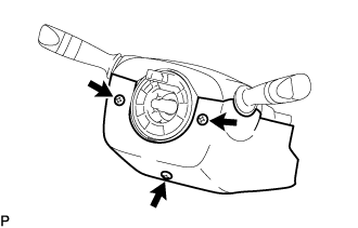
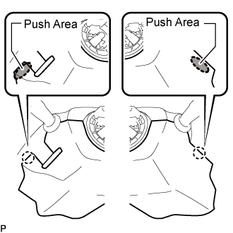
| 4. REMOVE LOWER STEERING COLUMN COVER |
Remove the 3 screws.
While pressing the push area shown in the illustration to detach the 2 claws, slightly lower steering column cover.
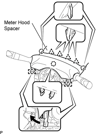
| 5. REMOVE UPPER STEERING COLUMN COVER |
Detach the 4 clips and 2 claws remove the meter hood spacer.
Detach the claw and 2 guide pin remove the upper steering column cover from the steering column assembly.
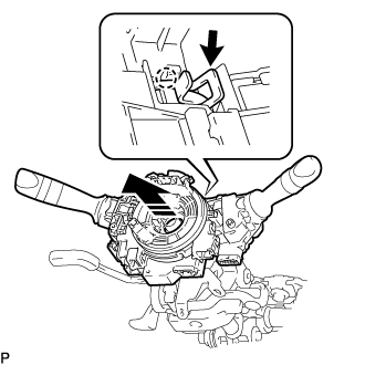
| 6. REMOVE COMBINATION SWITCH ASSEMBLY WITH SPIRAL CABLE SUB-ASSEMBLY |
Disconnect the connectors from the combination switch with spiral cable.
Using pliers, grip the claws of the clamp and remove the combination switch with spiral cable from the steering column.
| 7. REMOVE LOWER NO. 1 INSTRUMENT PANEL AIRBAG ASSEMBLY
(w/ Driver Side Knee Airbag) |
(Click here)
| 8. REMOVE LOWER INSTRUMENT PANEL SUB-ASSEMBLY (w/o Driver Side Knee Airbag) |
(Click here)
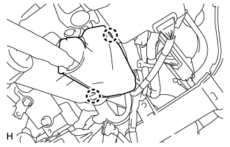
| 9. DISCONNECT WIRE HARNESS PROTECTOR AND WIRE HARNESS |
Remove the 2 wire harness cramps.
Detach the 2 claws to disconnect the wire harness protector and wire harness.
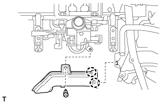
| 10. REMOVE NO. 3 AIR DUCT SUB-ASSEMBLY |
Remove the clip.
Detach the 2 claws and remove the duct.
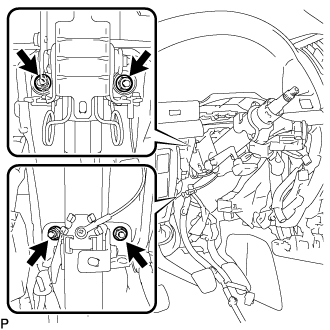
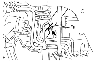
| 11. REMOVE STEERING COLUMN ASSEMBLY |
Put matchmarks on the steering intermediate shaft and the steering column.
Text in Illustration*a
| Matchmark
|
Remove the bolt.
w/o Entry and Start System:
Remove the 4 nuts and steering column.
w/ Entry and Start System:
Remove the 4 nuts and steering column.
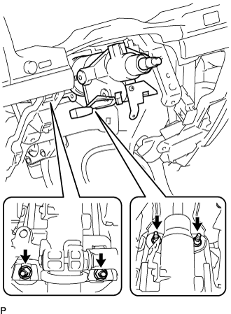
| 13. DISCONNECT STEERING INTERMEDIATE SHAFT ASSEMBLY |
Put matchmarks on the steering intermediate shaft and the No. 2 steering intermediate shaft.
Text in Illustration*a
| Matchmark
|
Remove the bolt, and then pull out the intermediate shaft toward the inside of the vehicle.
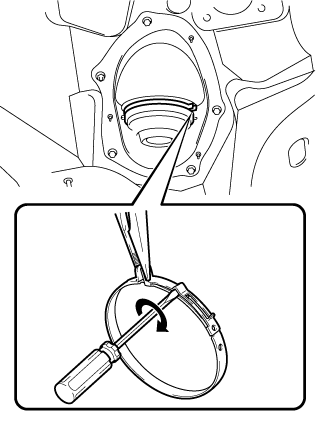
| 14. REMOVE STEERING COLUMN HOLE COVER SUB-ASSEMBLY |
Hold the clamp with needle nose pliers, then insert a screwdriver and turn it in the direction shown in the illustration to remove the clamp of the steering column hole cover.
Remove the 4 bolts and nut with the steering column hole cover from the vehicle.
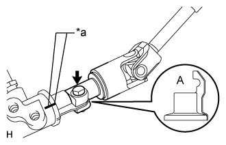
| 15. DISCONNECT NO. 2 STEERING INTERMEDIATE SHAFT |
Loosen the bolt and remove the No. 2 intermediate shaft.
Text in Illustration*a
| Matchmark
|
- NOTICE:
- It is possible to install the intermediate shaft to the same position it was removed from without placing matchmarks due to the dust cover part labeled A. Therefore, do not remove the dust cover from the steering link.
- HINT:
- If the dust cover is removed/installed or replaced, place matchmarks on the dust cover and steering link.