Power Tilt And Power Telescopic Steering Column System Actuator Power Source Circuit
Steering. Land Cruiser. Urj200, 202 Grj200 Vdj200
DESCRIPTION
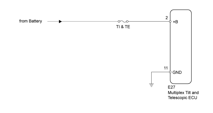
WIRING DIAGRAM
INSPECTION PROCEDURE
INSPECT FUSE (TI & TE)
CHECK HARNESS AND CONNECTOR (MULTIPLEX TILT AND TELESCOPIC ECU - BATTERY)
CHECK HARNESS AND CONNECTOR (MULTIPLEX TILT AND TELESCOPIC ECU - BODY GROUND)
POWER TILT AND POWER TELESCOPIC STEERING COLUMN SYSTEM - Actuator Power Source Circuit |
DESCRIPTION
This is the power source for the motors.
WIRING DIAGRAM
INSPECTION PROCEDURE
Remove the TI & TE fuse from the main body ECU.
Measure the resistance according to the value(s) in the table below.
- Standard Resistance:
Tester Connection
| Condition
| Specified Condition
|
TI & TE fuse
| Always
| Below 1 Ω
|
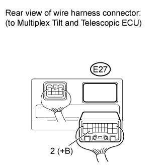
| 2.CHECK HARNESS AND CONNECTOR (MULTIPLEX TILT AND TELESCOPIC ECU - BATTERY) |
Disconnect the E27 multiplex tilt and telescopic ECU connector.
Measure the voltage according to the value(s) in the table below.
- Standard Voltage:
Tester Connection
| Condition
| Specified Condition
|
E27-2 (+B) - Body ground
| Always
| 11 to 14 V
|
| | REPAIR OR REPLACE HARNESS OR CONNECTOR |
|
|
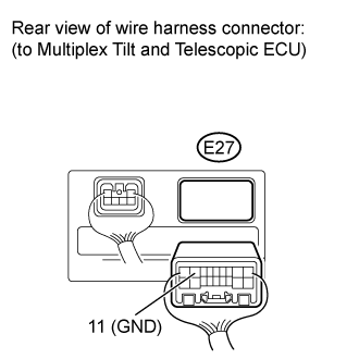
| 3.CHECK HARNESS AND CONNECTOR (MULTIPLEX TILT AND TELESCOPIC ECU - BODY GROUND) |
Measure the resistance according to the value(s) in the table below.
- Standard Resistance:
Tester Connection
| Condition
| Specified Condition
|
E27-11 (GND) - Body ground
| Always
| Below 1 Ω
|
| | REPAIR OR REPLACE HARNESS OR CONNECTOR |
|
|