Vehicle Stability Control System Turn Assist Indicator Light Circuit
Brake. Land Cruiser. Urj200, 202 Grj200 Vdj200
DESCRIPTION
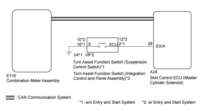
WIRING DIAGRAM
INSPECTION PROCEDURE
CHECK CAN COMMUNICATION LINE
CHECK DTC (CAN COMMUNICATION SYSTEM)
INSPECT SUSPENSION CONTROL SWITCH OR INTEGRATION CONTROL AND PANEL ASSEMBLY
CHECK HARNESS AND CONNECTOR (SKID CONTROL ECU - TURN ASSIST FUNCTION SWITCH)
CHECK HARNESS AND CONNECTOR (SKID CONTROL ECU EXI4 CIRCUIT)
CHECK HARNESS AND CONNECTOR (SKID CONTROL ECU EXI4 CIRCUIT)
VEHICLE STABILITY CONTROL SYSTEM - Turn Assist Indicator Light Circuit |
DESCRIPTION
When any of the following conditions are met, the turn assist system becomes operable and the turn assist indicator light illuminates.- Crawl Control is operating.
- The turn assist function switch (suspension control switch)*1 or turn assist function switch (integration control and panel assembly)*2 is on.
*1: w/o Entry and Start System
*2: w/ Entry and Start System
- The center differential is "free".
- The vehicle is moving at a speed of 10 km/h (6 mph) or less.
- The shift lever is not in P, R or N.
WIRING DIAGRAM
INSPECTION PROCEDURE
- NOTICE:
- After replacing the master cylinder solenoid, perform zero point calibration and store the system information (Click here).
| 1.CHECK CAN COMMUNICATION LINE |
Turn the ignition switch off.
Connect the GTS to the DLC3.
Turn the ignition switch to ON and the GTS on.
Select "CAN Bus Check" from the System Selection Menu screen, and follow the prompts on the screen to inspect the CAN Bus.
- OK:
- "CAN Bus Check" indicates no malfunctions in CAN communication.
ResultResult
| Proceed to
|
OK
| A
|
NG (for LHD (with Central Gateway ECU))
| B
|
NG (for LHD (without Central Gateway ECU))
| C
|
NG (for RHD (with Central Gateway ECU))
| D
|
NG (for RHD (without Central Gateway ECU))
| E
|
| | GO TO CAN COMMUNICATION SYSTEM (HOW TO PROCEED WITH TROUBLESHOOTING) (Click here) |
|
|
| | GO TO CAN COMMUNICATION SYSTEM (HOW TO PROCEED WITH TROUBLESHOOTING) (Click here) |
|
|
| | GO TO CAN COMMUNICATION SYSTEM (HOW TO PROCEED WITH TROUBLESHOOTING) (Click here) |
|
|
| | GO TO CAN COMMUNICATION SYSTEM (HOW TO PROCEED WITH TROUBLESHOOTING) (Click here) |
|
|
| 2.CHECK DTC (CAN COMMUNICATION SYSTEM) |
Turn the ignition switch off.
Connect the GTS to the DLC3.
Turn the ignition switch to ON and the GTS on.
for LHD (with Central Gateway ECU):
Check for DTCs (Click here).
for LHD (without Central Gateway ECU):
Check for DTCs (Click here).
for RHD (with Central Gateway ECU):
Check for DTCs (Click here).
for RHD (without Central Gateway ECU):
Check for DTCs (Click here).
ResultResult
| Proceed to
|
CAN DTC is not output
| A
|
CAN DTC is output (for LHD (with Central Gateway ECU))
| B
|
CAN DTC is output (for LHD (without Central Gateway ECU))
| C
|
CAN DTC is output (for RHD (with Central Gateway ECU))
| D
|
CAN DTC is output (for RHD (without Central Gateway ECU))
| E
|
| | GO TO CAN COMMUNICATION SYSTEM (HOW TO PROCEED WITH TROUBLESHOOTING) (Click here) |
|
|
| | GO TO CAN COMMUNICATION SYSTEM (HOW TO PROCEED WITH TROUBLESHOOTING) (Click here) |
|
|
| | GO TO CAN COMMUNICATION SYSTEM (HOW TO PROCEED WITH TROUBLESHOOTING) (Click here) |
|
|
| | GO TO CAN COMMUNICATION SYSTEM (HOW TO PROCEED WITH TROUBLESHOOTING) (Click here) |
|
|
| 3.INSPECT SUSPENSION CONTROL SWITCH OR INTEGRATION CONTROL AND PANEL ASSEMBLY |
w/o Entry and Start System:
Remove the turn assist function switch (suspension control switch) (Click here).
w/ Entry and Start System:
Remove the turn assist function switch (integration control and panel assembly) (Click here).
w/o Entry and Start System:
Inspect the turn assist function switch (suspension control switch) (Click here).
w/ Entry and Start System:
Inspect the turn assist function switch (integration control and panel assembly) (Click here).
ResultResult
| Proceed to
|
OK
| A
|
NG (w/o Entry and Start System)
| B
|
NG (w/ Entry and Start System)
| C
|
| |
|
| | REPLACE INTEGRATION CONTROL AND PANEL ASSEMBLY (Click here) |
|
|
| 4.CHECK HARNESS AND CONNECTOR (SKID CONTROL ECU - TURN ASSIST FUNCTION SWITCH) |
Turn the ignition switch off.
Disconnect the A24 skid control ECU (master cylinder solenoid) connector.
Disconnect the V4 turn assist function switch (suspension control switch)*1 or V8 turn assist function switch (integration control and panel assembly)*2 connector.
- *1: w/o Entry and Start System
- *2: w/ Entry and Start System
Measure the resistance according to the value(s) in the table below.
- Standard Resistance:
w/o Entry and Start System:Tester Connection
| Condition
| Specified Condition
|
A24-29 (EXI4) - V4-2 (ECU)
| Always
| Below 1 Ω
|
A24-29 (EXI4) - Body ground
| Always
| 10 kΩ or higher
|
V4-16 (E) - Body ground
| Always
| Below 1 Ω
|
w/ Entry and Start System:Tester Connection
| Condition
| Specified Condition
|
A24-29 (EXI4) - V8-12 (ECU)
| Always
| Below 1 Ω
|
A24-29 (EXI4) - Body ground
| Always
| 10 kΩ or higher
|
V8-10 (E) - Body ground
| Always
| Below 1 Ω
|
ResultResult
| Proceed to
|
OK (w/o Entry and Start System)
| A
|
OK (w/ Entry and Start System)
| B
|
NG
| C
|
| |
|
| | REPAIR OR REPLACE HARNESS OR CONNECTOR |
|
|
| 5.CHECK HARNESS AND CONNECTOR (SKID CONTROL ECU EXI4 CIRCUIT) |
Turn the ignition switch off.
Connect the skid control ECU (master cylinder solenoid) connector.
Disconnect the turn assist function switch (suspension control switch) connector.
Measure the voltage according to the value(s) in the table below.
- Standard Voltage:
Tester Connection
| Switch Condition
| Specified Condition
|
V4-2 (ECU) - Body ground
| Ignition switch ON
| 11 to 14 V
|
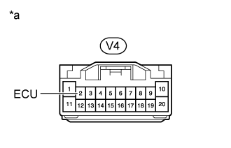
*a
| Front view of wire harness connector
(to Turn Assist Function Switch [Suspension Control Switch])
|
| OK |
|
|
|
| GO TO METER / GAUGE SYSTEM (HOW TO PROCEED WITH TROUBLESHOOTING) (Click here) |
|
| 6.CHECK HARNESS AND CONNECTOR (SKID CONTROL ECU EXI4 CIRCUIT) |
Turn the ignition switch off.
Connect the skid control ECU (master cylinder solenoid) connector.
Disconnect the turn assist function switch (integration control and panel assembly) connector.
Measure the voltage according to the value(s) in the table below.
- Standard Voltage:
Tester Connection
| Switch Condition
| Specified Condition
|
V8-12 (ECU) - Body ground
| Ignition switch ON
| 11 to 14 V
|
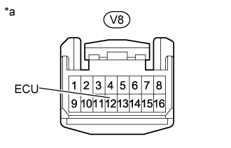
*a
| Front view of wire harness connector
(to Turn Assist Function Switch [Integration Control and Panel Assembly])
|
ResultResult
| Proceed to
|
OK
| A
|
NG (for LHD)
| B
|
NG (for RHD)
| C
|
| A |
|
|
|
| GO TO METER / GAUGE SYSTEM (HOW TO PROCEED WITH TROUBLESHOOTING) (Click here) |
|