Dtc C1432 Steering Angle Sensor Power Source Voltage Malfunction
Brake. Land Cruiser. Urj200, 202 Grj200 Vdj200
DESCRIPTION
WIRING DIAGRAM
INSPECTION PROCEDURE
CHECK DTC (CAN COMMUNICATION SYSTEM)
CHECK HARNESS AND CONNECTOR (IG/ESS TERMINAL)
CHECK HARNESS AND CONNECTOR (BAT TERMINAL)
CHECK HARNESS AND CONNECTOR (+BI TERMINAL)
CHECK HARNESS AND CONNECTOR (SPIRAL WITH SENSOR CABLE SUB-ASSEMBLY - STEERING CONTROL ECU)
DTC C1432 Steering Angle Sensor Power Source Voltage Malfunction |
DESCRIPTION
Steering angle sensor (Spiral with sensor cable sub-assembly) signals are sent to the skid control ECU (master cylinder solenoid) via the CAN communication system. When there is a malfunction in the CAN communication system, it is detected by the steering angle sensor zero point malfunction diagnostic function.DTC Code
| DTC Detection Condition
| Trouble Area
|
C1432
| A steering angle sensor power supply malfunction signal is received from the steering angle sensor.
| - J/B-B NO. 1 fuse
- ECU-IG NO. 1 fuse
- Steering angle sensor (Spiral with sensor cable sub-assembly) power supply
- Steering angle sensor (Spiral with sensor cable sub-assembly)
- VGRS ECU (Steering control ECU)*
|
- *: w/ VGRS System
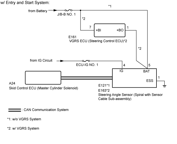
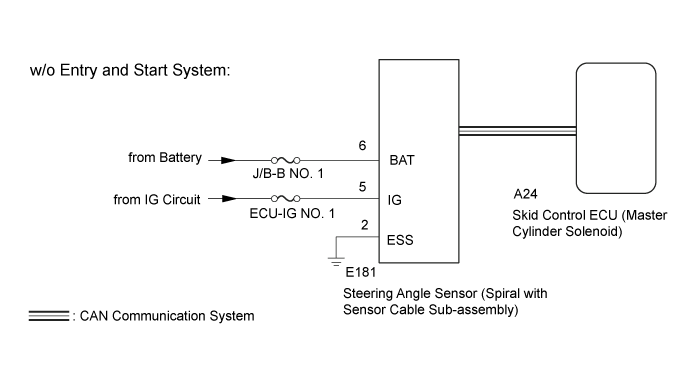
WIRING DIAGRAM
INSPECTION PROCEDURE
- NOTICE:
- When replacing the steering angle sensor (spiral with sensor cable sub-assembly), confirm that the replacement part is of the correct specification.
- Inspect the fuses for circuits related to this system before performing the following inspection procedure.
- HINT:
- When the speed sensor or the yaw rate and acceleration sensor (airbag sensor assembly) has trouble, DTCs for the steering angle sensor (spiral with sensor cable sub-assembly) may be stored even when the steering angle sensor is normal. When DTCs for the speed sensor or yaw rate and acceleration sensor (airbag sensor assembly) are output together with DTCs for the steering angle sensor (spiral with sensor cable sub-assembly), inspect and repair the speed sensor and yaw rate and acceleration sensor (airbag sensor assembly) first, and then inspect and repair the steering angle sensor (spiral with sensor cable sub-assembly).
| 1.CHECK DTC (CAN COMMUNICATION SYSTEM) |
for LHD (with Central Gateway ECU):
Check for DTCs (Click here).
for LHD (without Central Gateway ECU):
Check for DTCs (Click here).
for RHD (with Central Gateway ECU):
Check for DTCs (Click here).
for RHD (without Central Gateway ECU):
Check for DTCs (Click here).
ResultResult
| Proceed to
|
CAN DTC is not output
| A
|
CAN DTC is output (for LHD (with Central Gateway ECU))
| B
|
CAN DTC is output (for LHD (without Central Gateway ECU))
| C
|
CAN DTC is output (for RHD (with Central Gateway ECU))
| D
|
CAN DTC is output (for RHD (without Central Gateway ECU))
| E
|
| | GO TO CAN COMMUNICATION SYSTEM (HOW TO PROCEED WITH TROUBLESHOOTING) (Click here) |
|
|
| | GO TO CAN COMMUNICATION SYSTEM (HOW TO PROCEED WITH TROUBLESHOOTING) (Click here) |
|
|
| | GO TO CAN COMMUNICATION SYSTEM (HOW TO PROCEED WITH TROUBLESHOOTING) (Click here) |
|
|
| | GO TO CAN COMMUNICATION SYSTEM (HOW TO PROCEED WITH TROUBLESHOOTING) (Click here) |
|
|
| 2.CHECK HARNESS AND CONNECTOR (IG/ESS TERMINAL) |
Turn the ignition switch off.
Make sure that there is no looseness in the locking part and connecting part of the connectors.
w/o Entry and Start System:
Disconnect the steering angle sensor (spiral with sensor cable sub-assembly) connector.
Measure the voltage according to the value(s) in the table below.
- Standard Voltage:
Tester Connection
| Switch Condition
| Specified Condition
|
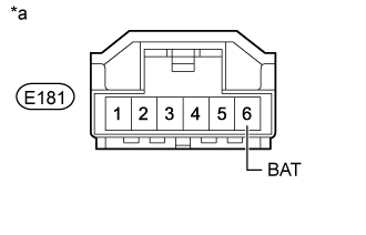
E181-5 (IG) - Body ground
| Ignition switch ON
| 11 to 14 V
|
Measure the resistance according to the value(s) in the table below.
- Standard Resistance:
Tester Connection
| Condition
| Specified Condition
|
E181-2 (ESS) - Body ground
| Always
| Below 1 Ω
|
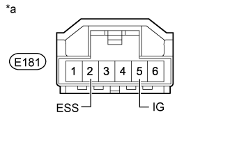
Text in Illustration*a
| Front view of wire harness connector
(to Steering Angle Sensor [Spiral with Sensor Cable Sub-assembly])
|
w/ Entry and Start System:
Disconnect the steering angle sensor (spiral with sensor cable sub-assembly) connector.
Measure the voltage according to the value(s) in the table below.
- Standard Voltage:
w/o VGRS System:Tester Connection
| Switch Condition
| Specified Condition
|
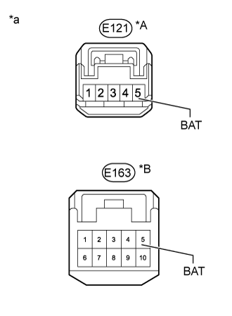
E121-4 (IG) - Body ground
| Ignition switch ON
| 11 to 14 V
|
w/ VGRS System:Tester Connection
| Switch Condition
| Specified Condition
|
E163-4 (IG) - Body ground
| Ignition switch ON
| 11 to 14 V
|
Measure the resistance according to the value(s) in the table below.
- Standard Resistance:
w/o VGRS System:Tester Connection
| Condition
| Specified Condition
|
E121-1 (ESS) - Body ground
| Always
| Below 1 Ω
|
w/ VGRS System:Tester Connection
| Condition
| Specified Condition
|
E163-1 (ESS) - Body ground
| Always
| Below 1 Ω
|
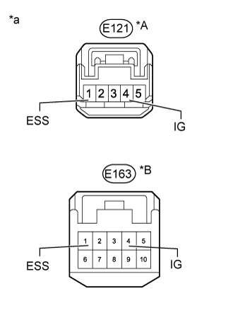
Text in Illustration*A
| w/o VGRS System
|
*B
| w/ VGRS System
|
*a
| Front view of wire harness connector
(to Steering Angle Sensor [Spiral with Sensor Cable Sub-assembly])
|
| | REPAIR OR REPLACE HARNESS OR CONNECTOR |
|
|
| 3.CHECK HARNESS AND CONNECTOR (BAT TERMINAL) |
Turn the ignition switch off.
w/o Entry and Start System:
Disconnect the steering angle sensor (spiral with sensor cable sub-assembly) connector.
Measure the voltage according to the value(s) in the table below.
- Standard Voltage:
Tester Connection
| Condition
| Specified Condition
|
E181-6 (BAT) - Body ground
| Always
| 11 to 14 V
|
Text in Illustration*a
| Front view of wire harness connector
(to Steering Angle Sensor [Spiral with Sensor Cable Sub-assembly])
|
w/ Entry and Start System:
Disconnect the steering angle sensor (spiral with sensor cable sub-assembly) connector.
Measure the voltage according to the value(s) in the table below.
- Standard Voltage:
w/o VGRS System:Tester Connection
| Condition
| Specified Condition
|
E121-5 (BAT) - Body ground
| Always
| 11 to 14 V
|
w/ VGRS System:Tester Connection
| Condition
| Specified Condition
|
E163-5 (BAT) - Body ground
| Always
| 11 to 14 V
|
Text in Illustration*A
| w/o VGRS System
|
*B
| w/ VGRS System
|
*a
| Front view of wire harness connector
(to Steering Angle Sensor [Spiral with Sensor Cable Sub-assembly])
|
ResultResult
| Proceed to
|
OK
| A
|
NG (w/ VGRS System)
| B
|
NG (w/o VGRS System)
| C
|
| |
|
| | REPAIR OR REPLACE HARNESS OR CONNECTOR |
|
|
| A |
|
|
|
| REPLACE SPIRAL WITH SENSOR CABLE SUB-ASSEMBLY (Click here) |
|
| 4.CHECK HARNESS AND CONNECTOR (+BI TERMINAL) |
Turn the ignition switch off.
Disconnect the VGRS ECU (steering control ECU) connector.
Measure the voltage according to the value(s) in the table below.
- Standard Voltage:
Tester Connection
| Condition
| Specified Condition
|
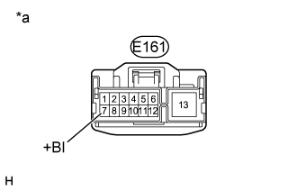
E161-7 (+BI) - Body ground
| Always
| 11 to 14 V
|
Text in Illustration*a
| Front view of wire harness connector
(to VGRS ECU [Steering Control ECU])
|
| | REPAIR OR REPLACE HARNESS OR CONNECTOR |
|
|
| 5.CHECK HARNESS AND CONNECTOR (SPIRAL WITH SENSOR CABLE SUB-ASSEMBLY - STEERING CONTROL ECU) |
Turn the ignition switch off.
Disconnect the E163 steering angle sensor (spiral with sensor cable sub-assembly) connector.
Disconnect the E161 VGRS ECU (steering control ECU) connector.
Measure the resistance according to the value(s) in the table below.
- Standard Resistance:
Tester Connection
| Condition
| Specified Condition
|
E163-5 (BAT) - E161-1 (+BO)
| Always
| Below 1 Ω
|
E163-5 (BAT) or E161-1 (+BO) - Body ground
| Always
| 10 kΩ or higher
|
ResultResult
| Proceed to
|
NG
| A
|
OK (for LHD)
| B
|
OK (for RHD)
| C
|
| A |
|
|
|
| REPAIR OR REPLACE HARNESS OR CONNECTOR |
|