INSTALL STABILIZER CONTROL WITH ACCUMULATOR HOUSING ASSEMBLY
TEMPORARILY INSTALL REAR NO. 1 STABILIZER CONTROL TUBE ASSEMBLY
TEMPORARILY INSTALL FRONT NO. 2 STABILIZER CONTROL TUBE ASSEMBLY
TEMPORARILY INSTALL FRONT NO. 2 AND REAR NO. 1 STABILIZER CONTROL TUBE ASSEMBLY
CLOSE STABILIZER CONTROL WITH ACCUMULATOR HOUSING SHUTTER VALVE
Stabilizer Control Valve (W/ Kdss) -- Installation |
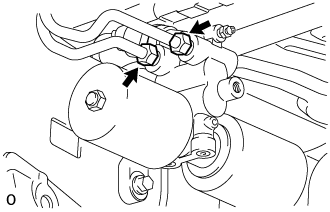
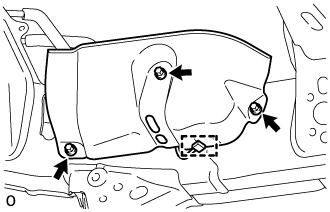
| 1. INSTALL STABILIZER CONTROL WITH ACCUMULATOR HOUSING ASSEMBLY |
Install the stabilizer control with accumulator housing with the 2 bolts.
- Torque:
- 32 N*m{326 kgf*cm, 24 ft.*lbf}
 |
Install the bleeder plug.
- Torque:
- 8.3 N*m{85 kgf*cm, 73 in.*lbf}
- HINT:
- The bleeder plug cap will be installed after bleeding air.
 |
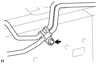
| 2. CONNECT REAR NO. 2 STABILIZER CONTROL TUBE ASSEMBLY |
Connect the rear No. 2 stabilizer control tube to the stabilizer control with accumulator housing.
 |
| 3. TEMPORARILY INSTALL REAR NO. 1 STABILIZER CONTROL TUBE ASSEMBLY |
Temporarily install the rear No. 1 stabilizer control tube to the stabilizer control with accumulator housing.
 |
Install the bolt to the vehicle.
- Torque:
- 29 N*m{296 kgf*cm, 21 ft.*lbf}
 |
| 4. TEMPORARILY INSTALL FRONT NO. 2 STABILIZER CONTROL TUBE ASSEMBLY |
Temporarily install the front No. 2 stabilizer control tube to the front No. 1 stabilizer control tube.
 |
Install the bolt to the vehicle.
- Torque:
- 29 N*m{296 kgf*cm, 21 ft.*lbf}
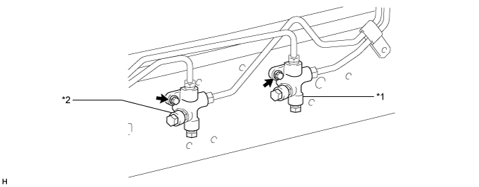
| 5. TEMPORARILY INSTALL FRONT NO. 2 AND REAR NO. 1 STABILIZER CONTROL TUBE ASSEMBLY |
Temporarily install the front No. 2 and rear No. 1 stabilizer control tube to the 2 stabilizer control adapters.
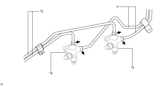
Text in Illustration *1 Rear No. 1 Stabilizer Control Tube *2 Front No. 2 Stabilizer Control Tube *3 Stabilizer Control Adapter for Upper Chamber Side *4 Stabilizer Control Adapter for Lower Chamber Side
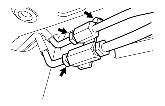
| 6. INSTALL STABILIZER CONTROL ADAPTER SUB-ASSEMBLY |
Install the 2 stabilizer control adapters to the vehicle with the 2 bolts.
Text in Illustration *1 Stabilizer Control Adapter for Upper Chamber Side *2 Stabilizer Control Adapter for Lower Chamber Side - Torque:
- 32 N*m{326 kgf*cm, 24 ft.*lbf}
| 7. TIGHTEN REAR NO. 1 STABILIZER CONTROL TUBE ASSEMBLY |
Using a union nut wrench, tighten the rear No. 1 stabilizer control tube.
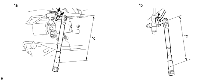
Text in Illustration *a Stabilizer Control with Accumulator Housing Side *b Stabilizer Control Adapter Side *c Torque Wrench Fulcrum Length - - - Torque:
- Specified tightening torque:
- 44 N*m{450 kgf*cm, 33 ft.*lbf}
- HINT:
- Calculate the torque wrench reading when changing the fulcrum length of the torque wrench (Click here).
- When using a union nut wrench (fulcrum length of 30 mm (1.181 in.)) + torque wrench (fulcrum length of 255 mm (10.039 in.)): 40 N*m (403 kgf*cm, 29 ft.*lbf)
| 8. TIGHTEN FRONT NO. 2 STABILIZER CONTROL TUBE ASSEMBLY |
Using a union nut wrench, tighten the front No. 2 stabilizer control tube.
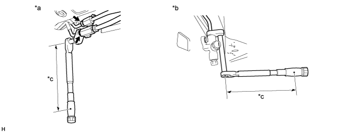
Text in Illustration *a Front No. 1 Stabilizer Control Tube Side *b Stabilizer Control Adapter Side *c Torque Wrench Fulcrum Length - - - Torque:
- Specified tightening torque:
- 44 N*m{450 kgf*cm, 33 ft.*lbf}
- HINT:
- Calculate the torque wrench reading when changing the fulcrum length of the torque wrench (Click here).
- When using a union nut wrench (fulcrum length of 30 mm (1.181 in.)) + torque wrench (fulcrum length of 255 mm (10.039 in.)): 40 N*m (403 kgf*cm, 29 ft.*lbf)
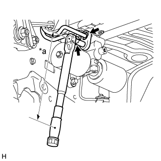
| 9. TIGHTEN REAR NO. 2 STABILIZER CONTROL TUBE ASSEMBLY |
Using a union nut wrench, tighten the rear No. 2 stabilizer control tube.
Text in Illustration *a Torque Wrench Fulcrum Length - Torque:
- Specified tightening torque:
- 44 N*m{450 kgf*cm, 33 ft.*lbf}
- HINT:
- Calculate the torque wrench reading when changing the fulcrum length of the torque wrench (Click here).
- When using a union nut wrench (fulcrum length of 30 mm (1.181 in.)) + torque wrench (fulcrum length of 255 mm (10.039 in.)): 40 N*m (403 kgf*cm, 29 ft.*lbf)
 |
| 10. INSTALL CENTER EXHAUST PIPE ASSEMBLY |
for 1GR-FE:
Install the center exhaust pipe (Click here).
for 1UR-FE:
Install the center exhaust pipe (Click here).
for 3UR-FE:
Install the center exhaust pipe (Click here).
for 1VD-FTV:
Install the center exhaust pipe (Click here).
| 11. INSTALL TAILPIPE ASSEMBLY |
for 1GR-FE:
Install the tailpipe (Click here).
for 1UR-FE:
Install the tailpipe (Click here).
for 3UR-FE:
Install the tailpipe (Click here).
for 1VD-FTV:
Install the tailpipe (Click here).
| 12. BLEED AIR FROM SUSPENSION FLUID |
Bleed the air from the suspension fluid (Click here).
| 13. INSPECT FOR SUSPENSION FLUID LEAK |
- CAUTION:
- Fluid is pumped into the system at a high pressure of approximately 3 MPa (30.6 kgf/cm2, 435 psi). If a fluid leak is discovered, immediately release the pressure and repair the fluid leak.
Perform a driving test.
Check for fluid leakage from the parts and connections.

| 14. INSPECT FOR EXHAUST GAS LEAK |
- If gas is leaking, tighten the areas necessary to stop the leak. Replace damaged parts as necessary.
| 15. MEASURE VEHICLE HEIGHT |
- NOTICE:
- Perform the inspection on a level surface.
- Ensure that the wheels are on the ground and facing straight ahead.
- Perform the inspection with the vehicle load completely on the suspension.
- HINT:
- Perform this step with the fuel tank full.
- If there are any parts installed to the vehicle which place any unbalanced load on the left or right side of the vehicle, remove them.
Set the tire pressure to the specified value(s) (Click here).
Bounce the vehicle to stabilize the suspension.
Measure the distance from the ground to the top of the bumper and calculate the difference in the vehicle height between left and right. Perform this procedure for both the front and rear wheels.
- Height difference of left and right sides:
- 15 mm (0.591 in.) or less
- HINT:
- If not as specified, perform the vehicle tilt calibration.
 |
| 16. CLOSE STABILIZER CONTROL WITH ACCUMULATOR HOUSING SHUTTER VALVE |
- NOTICE:
- Perform the inspection on a level surface.
- Ensure that the wheels are on the ground and facing straight ahead.
- Perform the inspection with the vehicle load completely on the suspension.
- HINT:
- Perform this step with the fuel tank full.
- If there are any parts installed to the vehicle which place any unbalanced load on the left or right side of the vehicle, remove them.
Using a 5 mm hexagon socket wrench, tighten the lower and upper chamber shutter valves of the stabilizer control with accumulator housing.
- Torque:
- 14 N*m{140 kgf*cm, 10 ft.*lbf}
| 17. INSTALL STABILIZER CONTROL VALVE PROTECTOR |
 |
Install the valve protector with the 3 bolts.
- Torque:
- 18 N*m{184 kgf*cm, 13 ft.*lbf}
Attach the clamp, and connect the connector to the valve protector.