Dtc C1782 Power Source Voltage Malfunction
Suspension. Land Cruiser. Urj200, 202 Grj200 Vdj200
DESCRIPTION
WIRING DIAGRAM
INSPECTION PROCEDURE
READ VALUE USING GTS (IG VOLTAGE)
RECONFIRM DTC OUTPUT
READ VALUE USING GTS (+B POWER SOURCE VOLTAGE, +B2 POWER SOURCE VOLTAGE)
INSPECT FUSE (AHC-B, AHC-B NO. 2)
CHECK HARNESS AND CONNECTOR (BATTERY - SUSPENSION CONTROL ECU)
CHECK HARNESS AND CONNECTOR (BATTERY - ECU AND BODY GROUND)
DTC C1782 Power Source Voltage Malfunction |
DESCRIPTION
DTC Code
| Detection Condition
| Trouble Area
|
C1782
| While the engine switch is on (IG), voltage at terminal IG, BAT and/or BAT2 is 10 V or less, or 16 V or more for 0.5 seconds.
| - Battery
- Charging system
- Harness or connector
- AHC-B fuse
- AHC-B No. 2 fuse
- Suspension control ECU
|
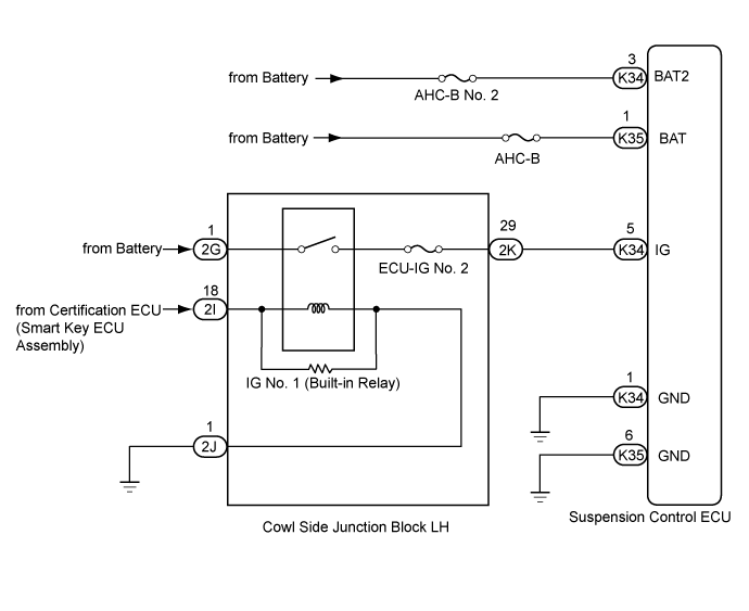
WIRING DIAGRAM
INSPECTION PROCEDURE
- NOTICE:
- Even if DTC C1781 is stored at the same time, perform the inspection for DTC C1782 first.
- Before performing troubleshooting, inspect the connectors of related circuits.
- If the suspension control ECU or height control sensor is replaced, the vehicle height offset calibration must be performed (Click here).
| 1.READ VALUE USING GTS (IG VOLTAGE) |
Connect the GTS to the DLC3.
Turn the engine switch on (IG) and the GTS on.
Read the "IG Power Source Voltage" item in the Data List.
AHCTester Display
| Measurement Item/Range
| Normal Condition
| Diagnostic Note
|
IG Power Source Voltage
| Power supply voltage /
min.: 0 V
max.: 255 V
| Engine switch on (IG): 11 to 14 V
| -
|
- OK:
- 11 to 14 V
Clear the DTCs (Click here).
Check for DTCs.
ResultResult
| Proceed to
|
DTC is output
| A
|
DTC is not output
| B
|
| 3.READ VALUE USING GTS (+B POWER SOURCE VOLTAGE, +B2 POWER SOURCE VOLTAGE) |
Connect the GTS to the DLC3.
Turn the engine switch on (IG) and the GTS on.
Read the "+B Power Source Voltage" and "+B2 Power Source Voltage" items in the Data List.
AHCTester Display
| Measurement Item/Range
| Normal Condition
| Diagnostic Note
|
+B Power Source Voltage
| Power supply for absorber control actuator /
min.: 0 V
max.: 255 V
| Engine switch on (IG): 11 to 14 V
| -
|
+B2 Power Source Voltage
| Power supply for No. 1 height control valve and front suspension control valve /
min.: 0 V
max.: 255 V
| Engine switch on (IG): 11 to 14 V
| -
|
- OK:
- 11 to 14 V
| 4.INSPECT FUSE (AHC-B, AHC-B NO. 2) |
Remove the AHC-B and AHC-B No. 2 fuses from the cowl side junction block RH.
Measure the resistance according to the value(s) in the table below.
- Standard Resistance:
Tester Connection
| Condition
| Specified Condition
|
AHC-B fuse
| Always
| Below 1 Ω
|
AHC-B No. 2 fuse
| Always
| Below 1 Ω
|
| | CHECK FOR SHORT IN ALL HARNESSES AND CONNECTORS CONNECTED TO FUSE AND REPLACE FUSE |
|
|
| 5.CHECK HARNESS AND CONNECTOR (BATTERY - SUSPENSION CONTROL ECU) |
Disconnect the K34 and K35 ECU connectors.
Measure the voltage according to the value(s) in the table below.
- Standard Voltage:
Tester Connection
| Switch Condition
| Specified Condition
|
K34-3 (BAT2) - Body ground
| Engine switch on (IG)
| 11 to 14 V
|
K35-1 (BAT) - Body ground
| Engine switch on (IG)
| 11 to 14 V
|
| | REPAIR OR REPLACE HARNESS OR CONNECTOR |
|
|
| 6.CHECK HARNESS AND CONNECTOR (BATTERY - ECU AND BODY GROUND) |
Disconnect the K34 ECU connector.
Measure the voltage according to the value(s) in the table below.
- Standard Voltage:
Tester Connection
| Switch Condition
| Specified Condition
|
K34-5 (IG) - Body ground
| Engine switch on (IG)
| 11 to 14 V
|
ResultResult
| Proceed to
|
OK
| A
|
NG (1UR-FE)
| B
|
NG (1VD-FTV)
| C
|
NG (3UR-FE)
| D
|
| | BATTERY VOLTAGE IS LOW OR CHARGING SYSTEM HAS MALFUNCTION |
|
|
| | BATTERY VOLTAGE IS LOW OR CHARGING SYSTEM HAS MALFUNCTION |
|
|
| | BATTERY VOLTAGE IS LOW OR CHARGING SYSTEM HAS MALFUNCTION |
|
|