INSTALL MANUAL TRANSMISSION WITH TRANSFER ASSEMBLY (for H150F)
INSTALL AUTOMATIC TRANSMISSION WITH TRANSFER ASSEMBLY (for AB60F)
INSTALL AUTOMATIC TRANSMISSION WITH TRANSFER ASSEMBLY (for A750F)
CONNECT FLOOR SHIFT GEAR SHIFTING ROD SUB-ASSEMBLY (for AE80F)
INSTALL FRONT FENDER SPLASH SHIELD SUB-ASSEMBLY LH (for AE80F)
INSTALL FRONT FENDER SPLASH SHIELD SUB-ASSEMBLY RH (for AE80F)
Transfer Assembly -- Installation |
| 1. INSTALL TRANSFER ASSEMBLY (for A750F, AB60F, H150F) |
Install the transfer assembly with the 8 bolts.
- Torque:
- 40 N*m{408 kgf*cm, 30 ft.*lbf}
- NOTICE:
- Take care not to damage the adaptor oil seal with the transfer input shaft spline.
| 2. INSTALL MANUAL TRANSMISSION WITH TRANSFER ASSEMBLY (for H150F) |
| 3. INSTALL AUTOMATIC TRANSMISSION WITH TRANSFER ASSEMBLY (for AB60F) |
- for 1VD-FTV: (Click here)
- for 1UR-FE: (Click here)
| 4. INSTALL AUTOMATIC TRANSMISSION WITH TRANSFER ASSEMBLY (for A750F) |
| 5. INSTALL TRANSFER ASSEMBLY (for AE80F) |
Install the transfer assembly with the 8 bolts.
- Torque:
- 40 N*m{408 kgf*cm, 30 ft.*lbf}
- NOTICE:
- Take care not to damage the adaptor oil seal with the transfer input shaft spline.
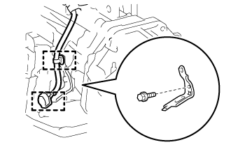
Install the bracket with the bolt.
- Torque:
- 29 N*m{296 kgf*cm, 21 ft.*lbf}
 |
Attach the 2 clamps.
w/ Temperature Sensor:
Connect the 3 connectors and attach the 3 clamps.
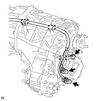 |
w/o Temperature Sensor:
Connect the 2 connectors and attach the 3 clamps.
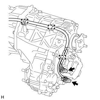 |
Connect the transfer breather hose sub-assembly and attach the 2 clamps.
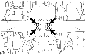
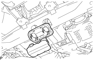
| 6. INSTALL REAR NO. 1 ENGINE MOUNTING INSULATOR (for AE80F) |
Install the rear No. 1 engine mounting insulator to the transmission with the 4 bolts.
- Torque:
- 59 N*m{602 kgf*cm, 44 ft.*lbf}
 |
Install the engine mounting heat insulator with the 2 bolts.
- Torque:
- 12 N*m{122 kgf*cm, 9 ft.*lbf}
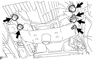
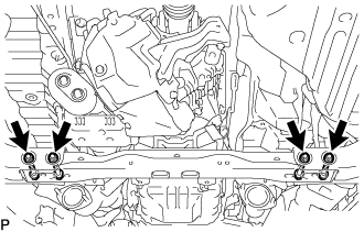
| 7. INSTALL NO. 2 FRAME CROSSMEMBER SUB-ASSEMBLY (for AE80F) |
Temporarily install the No. 2 frame crossmember sub-assembly to the frame with the 4 bolts and 4 nuts.
 |
Lower the transmission assembly, and then install the rear No. 1 engine mounting insulator to the No. 2 frame crossmember sub-assembly with the 4 bolts.
- Torque:
- 37 N*m{377 kgf*cm, 27 ft.*lbf}
 |
Tighten the No. 2 frame crossmember sub-assembly with the 4 bolts and 4 nuts.
- Torque:
- 110 N*m{1122 kgf*cm, 81 ft.*lbf}
w/ Cover:
Install the engine mounting hole cover.
 |
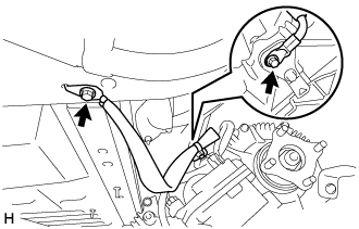
| 8. INSTALL GROUND WIRE (for AE80F) |
Install the ground wire with the 2 bolts.
- Torque:
- for Transfer Side:
- 8.0 N*m{82 kgf*cm, 71 in.*lbf}
- for Vehicle Side:
- 8.4 N*m{85 kgf*cm, 74 in.*lbf}
 |
| 9. CONNECT OIL COOLER TUBE (for AE80F) |
Install the transmission oil cooler tube clamp sub-assembly with bolt (labeled C).
- Torque:
- 14 N*m{143 kgf*cm, 10 ft.*lbf}
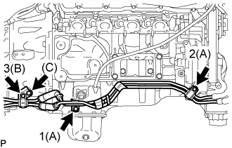 |
Temporarily install the oil cooler tube with the 3 bolts and 2 oil cooler tube unions.
Tighten the 3 bolts in the sequence shown in the illustration.
- Torque:
- for bolt A:
- 14 N*m{143 kgf*cm, 10 ft.*lbf}
- for bolt B:
- 8.0 N*m{82 kgf*cm, 71 in.*lbf}
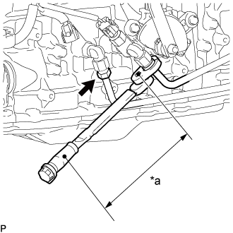
Tighten the 2 oil cooler tubes.
- Torque:
- Specified tightening torque:
- 34 N*m{347 kgf*cm, 25 ft.*lbf}
- HINT:
- Calculate the torque wrench reading when changing the fulcrum length of the torque wrench.
(Click here) - When using 17 mm union nut wrench (fulcrum length of 30 mm (1.18 in.)) + torque wrench (fulcrum length of 180 mm (7.09 in.)): 29 N*m (297 kgf*cm, 21 ft.*lbf)
Text in Illustration *a Torque Wrench Fulcrum Length
 |
| 10. INSTALL FRONT EXHAUST PIPE ASSEMBLY (for AE80F) |
| 11. INSTALL PROPELLER SHAFT ASSEMBLY (for AE80F) |
| 12. INSTALL FRONT PROPELLER SHAFT ASSEMBLY (for AE80F) |
| 13. CONNECT FLOOR SHIFT GEAR SHIFTING ROD SUB-ASSEMBLY (for AE80F) |
Turn the transmission control shaft lever of the park/neutral position switch counterclockwise until it stops, and then turn it clockwise 2 notches to set it to the N position.
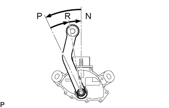 |
Move the shift lever to N.
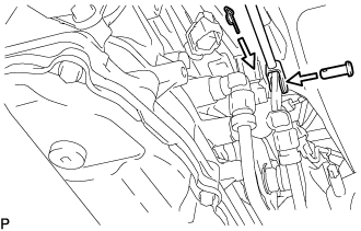
Connect the floor shift gear shifting rod sub-assembly to the transmission control shaft lever with the pin and a new clip.
 |
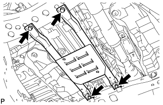
| 14. INSTALL OIL PAN PROTECTOR ASSEMBLY (for AE80F) |
Install the oil pan protector with the 4 bolts.
- Torque:
- 50 N*m{510 kgf*cm, 37 ft.*lbf}
 |
| 15. ADD TRANSFER OIL |
| 16. CHECK FOR TRANSFER OIL LEAK |
| 17. INSTALL NO. 2 ENGINE UNDER COVER (for AE80F) |
Install the No. 2 engine under cover with the 2 bolts.
- Torque:
- 29 N*m{296 kgf*cm, 21 ft.*lbf}
| 18. INSTALL NO. 1 ENGINE UNDER COVER SUB-ASSEMBLY (for AE80F) |
Install the No. 1 engine under cover with the 10 bolts.
- Torque:
- 29 N*m{296 kgf*cm, 21 ft.*lbf}
| 19. INSTALL FRONT FENDER SPLASH SHIELD SUB-ASSEMBLY LH (for AE80F) |
Push in the clip to install the front fender splash shield sub-assembly LH.
Install the 3 bolts and screw.
| 20. INSTALL FRONT FENDER SPLASH SHIELD SUB-ASSEMBLY RH (for AE80F) |
Push in the clip to install the front fender splash shield sub-assembly RH.
Install the 3 bolts and 2 screws.