Dtc P17C3 Rear Differential Lock Limit Sw Circuit
Drivetrain. Land Cruiser. Urj200, 202 Grj200 Vdj200
DESCRIPTION
WIRING DIAGRAM
INSPECTION PROCEDURE
CHECK HARNESS AND CONNECTOR (4 WHEEL DRIVE CONTROL ECU -
DIFFERENTIAL LOCK SHIFT ACTUATOR)
CHECK 4 WHEEL DRIVE CONTROL ECU (ECU OUTPUT VOLTAGE)
DTC P17C3 Rear Differential Lock Limit SW Circuit |
DESCRIPTION
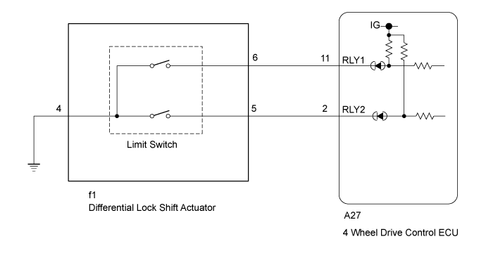
When the differential lock shift actuator is switching between free and lock, the RLY1 and RLY2 terminals are in one of the ON/OFF combinations listed in the table below.Terminal
| Mode
|
FREE
| Switching
| LOCK
|
RLY1
| ON
| ON
| OFF
|
RLY2
| OFF
| ON
| ON
|
A malfunction is detected depending on the combination of the 2 circuits that make up the limit switch of the differential lock shift actuator assembly.DTC No.
| DTC Detection Condition
- Diagnosis Condition
- Malfunction Status
- Malfunction Time
- Other
| Trouble Area
|
P17C3
| - When rear differential is switching between free and lock (differential lock shift motor operating) with ignition switch turned to ON
- The combination of RLY1 and RLY2 does not match
- 0 seconds
- 1 trip detection logic
| - Wire harness and connector
- 4 wheel drive control ECU
- Differential lock shift actuator
|
WIRING DIAGRAM
INSPECTION PROCEDURE
| 1.CHECK HARNESS AND CONNECTOR (4 WHEEL DRIVE CONTROL ECU -
DIFFERENTIAL LOCK SHIFT ACTUATOR) |
Disconnect the A27 4 wheel drive control ECU connector.
Disconnect the f1 differential lock shift actuator connector.
Measure the resistance according to the value(s) in the table below.
- Standard Resistance:
Tester Connection
| Condition
| Specified Condition
|
A27-11 (RLY1) - f1-6
| Always
| Below 1 Ω
|
A27-2 (RLY2) - f1-5
| Always
| Below 1 Ω
|
f1-4 - Body ground
| Always
| Below 1 Ω
|
A27-11 (RLY1) or f1-6 - Body ground
| Always
| 10 kΩ or higher
|
A27-2 (RLY2) or f1-5 - Body ground
| Always
| 10 kΩ or higher
|
| | REPAIR OR REPLACE HARNESS OR CONNECTOR |
|
|
| 2.CHECK 4 WHEEL DRIVE CONTROL ECU (ECU OUTPUT VOLTAGE) |
Disconnect the f1 differential lock shift actuator connector.
Measure the voltage according to the value(s) in the table below.
- Standard Voltage:
Tester Connection
| Switch Condition
| Specified Condition
|
f1-6 - Body ground
| Ignition switch ON
| 10 to 14 V
|
f1-5 - Body ground
| Ignition switch ON
| 10 to 14 V
|
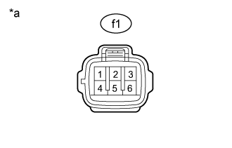
Text in Illustration*a
| Front view of wire harness connector
(to Differential Lock Shift Actuator)
|
- Result:
Result
| Proceed to
|
OK
| A
|
NG
| for LHD
| B
|
for RHD
| C
|
| A |
|
|
|
| REPLACE DIFFERENTIAL LOCK SHIFT ACTUATOR (Click here) |
|