Automatic Transmission System Pattern Select Switch 2Nd Start Mode Circuit
Drivetrain. Land Cruiser. Urj200, 202 Grj200 Vdj200
DESCRIPTION
WIRING DIAGRAM
INSPECTION PROCEDURE
DRIVING TEST
INSPECT ECT 2ND SWITCH (INTEGRATION CONTROL AND PANEL ASSEMBLY)
CHECK HARNESS AND CONNECTOR (INTEGRATION CONTROL AND PANEL ASSEMBLY - BODY GROUND)
CHECK HARNESS AND CONNECTOR (INTEGRATION CONTROL AND PANEL ASSEMBLY - ECM)
AUTOMATIC TRANSMISSION SYSTEM - Pattern Select Switch 2nd Start Mode Circuit |
DESCRIPTION
When 2nd start mode is selected with the ECT 2nd switch (integration control and panel assembly), the ECM controls the shift solenoid valves and the transmission starts from 2nd gear.
WIRING DIAGRAM
Refer to Pattern Select Switch Power Mode Circuit (Click here).
INSPECTION PROCEDURE
- HINT:
- The driving test should be performed on a paved road (nonskid road).
Start the engine.
Turn the ECT 2nd switch off (normal drive mode).
Confirm vehicle response by driving from a parked position to fully depressing the accelerator pedal.
Turn the ECT 2nd switch on (2nd start mode) and perform the same check as above.
When driving the vehicle with the 2nd start mode on and off, check that there is a difference in acceleration.
- OK:
- There is a difference in acceleration.
| OK |
|
|
|
| PROCEED TO NEXT SUSPECTED AREA SHOWN IN PROBLEM SYMPTOMS TABLE (Click here) |
|
| 2.INSPECT ECT 2ND SWITCH (INTEGRATION CONTROL AND PANEL ASSEMBLY) |
Remove the integration control and panel assembly (Click here).
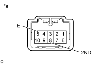
Measure the resistance according to the value(s) in the table below.
- Standard Resistance:
Tester Connection
| Switch Condition
| Specified Condition
|
8 (2ND) - 5 (E)
| ECT 2nd switch on
| Below 1 Ω
|
8 (2ND) - 5 (E)
| ECT 2nd switch off
| 10 kΩ or higher
|
Text in Illustration*a
| Component without harness connected
(Integration Control and Panel Assembly)
|
| | REPLACE INTEGRATION CONTROL AND PANEL ASSEMBLY (Click here) |
|
|
| 3.CHECK HARNESS AND CONNECTOR (INTEGRATION CONTROL AND PANEL ASSEMBLY - BODY GROUND) |
Disconnect the integration control and panel assembly connector.
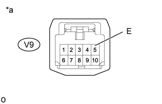
Measure the resistance according to the value(s) in the table below.
- Standard Resistance:
Tester Connection
| Condition
| Specified Condition
|
V9-5 (E) - Body ground
| Always
| Below 1 Ω
|
Text in Illustration*a
| Front view of wire harness connector
(to Integration Control and Panel Assembly)
|
| | REPAIR OR REPLACE HARNESS OR CONNECTOR |
|
|
| 4.CHECK HARNESS AND CONNECTOR (INTEGRATION CONTROL AND PANEL ASSEMBLY - ECM) |
Disconnect the ECM connector.
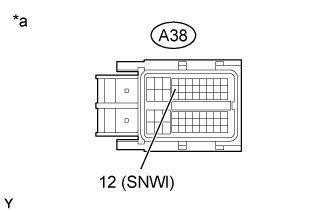
Measure the resistance according to the value(s) in the table below.
- Standard Resistance:
Tester Connection
| Switch Condition
| Specified Condition
|
A38-12 (SNWI) - Body ground
| ECT 2nd switch on
| Below 1 Ω
|
A38-12 (SNWI) - Body ground
| ECT 2nd switch off
| 10 kΩ or higher
|
Text in Illustration*a
| Front view of wire harness connector
(to ECM)
|
| | REPAIR OR REPLACE HARNESS OR CONNECTOR |
|
|
| OK |
|
|
|
| PROCEED TO NEXT SUSPECTED AREA SHOWN IN PROBLEM SYMPTOMS TABLE (Click here) |
|