Drivetrain. Land Cruiser. Urj200, 202 Grj200 Vdj200
Ab60F Automatic Transmission Transaxle. Land Cruiser. Urj200, 202 Grj200 Vdj200
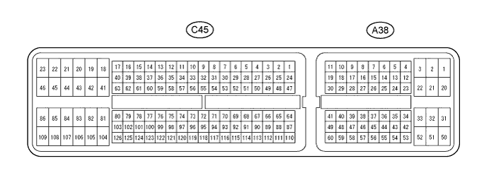
Automatic Transmission System (For 3Ur-Fe) -- Terminals Of Ecm |
| CHECK ECM |
- HINT:
- Each ECM terminal's standard voltage is shown in the table below.
- In the table, first follow the information under "Condition". Look under "Terminal No. (Symbol)" for the terminals to be inspected. The standard voltage between the terminals is shown under "Specified Condition".
- Use the illustration above as a reference for the ECM terminals.
| Terminal No. (Symbol) | Wiring Color | Terminal Description | Condition | Specified Condition |
| A38-21 (L4) - C45-81 (E1) | BR-R - W-B | 4L position signal |
| Below 1.5 V |
| 11 to 14 V | |||
| A38-5 (TFN) - C45-81 (E1) | G - W-B | N shift position switch signal |
| Below 1.5 V |
| 11 to 14 V | |||
| C45-120 (NSW) - C45-81 (E1) | L - W-B | PNP switch signal |
| Below 1 V |
| 11 to 14 V | |||
| C45-2 (P) - C45-81 (E1) | G-B - W-B | P shift position switch signal |
| 11 to 14 V |
| Below 1 V | |||
| C45-26 (R) - C45-81 (E1) | L-R - W-B | R shift position switch signal |
| 11 to 14 V |
| Below 1 V | |||
| C45-25 (N) - C45-81 (E1) | G-W - W-B | N shift position switch signal |
| 11 to 14 V |
| Below 1 V | |||
| C45-27 (D) - C45-81 (E1) | G - W-B | D shift position switch signal |
| 11 to 14 V |
| Below 1 V | |||
| A38-25 (S) - C45-81 (E1) | W - W-B | S shift position switch signal |
| 11 to 14 V |
| Below 1 V | |||
| A38-38 (SFTU) - C45-81 (E1) | V - W-B | Up-shift shift position switch signal |
| 11 to 14 V |
| Below 1 V | |||
| A38-27 (SFTD) - C45-81 (E1) | L - W-B | Down-shift position switch signal |
| 11 to 14 V |
| Below 1 V | |||
| C45-7 (S1) - C45-81 (E1) | R - W-B | S1 solenoid signal | 1st gear | Below 1 V |
| Not on 1st gear | 11 to 14 V | |||
| C45-6 (S2) - C45-81 (E1) | W - W-B | S2 solenoid signal | 1st, 2nd or 6th gear | 11 to 14 V |
| 3rd, 4th or 5th gear | Below 1 V | |||
| C45-3 (S3) - C45-81 (E1) | B-R - W-B | S3 solenoid signal | 1st, 2nd or 3rd gear | 11 to 14 V |
| 4th, 5th or 6th gear | Below 1 V | |||
| C45-5 (S4) - C45-81 (E1) | G-R - W-B | S4 solenoid signal | 5th or 6th gear | 11 to 14 V |
| 1st, 2nd, 3rd or 4th gear | Below 1 V | |||
| C45-4 (SR) - C45-81 (E1) | G - W-B | SR solenoid signal | 1st, 2nd, 3rd or 4th gear | 11 to 14 V |
| 5th or 6th gear | Below 1 V | |||
| C45-14 (SL1+) - C45-15 (SL1-) | Y - L | SL1 solenoid signal | 5th or 6th gear | Pulse generation |
| C45-12 (SL2+) - C45-13 (SL2-) | G-R - L-W | SL2 solenoid signal | Engine is idling | Pulse generation |
| C45-9 (SLT+) - C45-8 (SLT-) | B - G-B | SLT solenoid signal | Engine is idling | Pulse generation |
| C45-10 (SLU+) - C45-11 (SLU-) | L-Y - L-R | SLU solenoid signal | 5th gear (lock-up) or 6th gear (lock-up) | Pulse generation |
| C45-122 (THO1) - C45-98 (ETHA) | G-Y - BR | No. 1 ATF temperature sensor signal | No. 1 ATF temperature: 115°C (239°F) or higher | Below 1.5 V |
| C45-99 (THO2) - C45-98 (ETHA) | L - BR | No. 2 ATF temperature sensor signal | No. 2 ATF temperature: 115°C (239°F) or higher | Below 1.5 V |
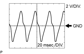
| C45-101 (SP2+) - C45-100 (SP2-) | Y - B | Speed sensor SP2 signal | Vehicle speed 20 km/h (12 mph) | Pulse generation (see waveform 1) |
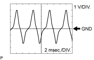
| C45-124 (NT+) - C45-123 (NT-) | Y - B | Speed sensor NT signal | Engine is idling (shift lever in P or N) | Pulse generation (see waveform 2) |
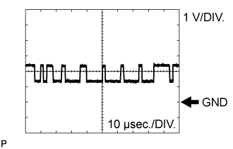
| A38-10 (CANH) - C45-81 (E1) | P - W-B | CAN communication line | Engine switch on (IG) | Pulse generation (see waveform 3) |
| A38-11 (CANL) - C45-81 (E1) | B - W-B | CAN communication line | Engine switch on (IG) | Pulse generation (see waveform 4) |
| A38-51 (PWR) - C45-81 (E1) | L-B - W-B | Pattern select (PWR) switch signal |
| 11 to 14 V |
| Below 1.5 V | |||
| A38-4 (SNWI) - C45-81 (E1) | P - W-B | Pattern select (2nd) switch signal |
| 11 to 14 V |
| Below 1.5 V |
Using an oscilloscope, check waveform 1.
Reference Terminal No. (Symbol) Tool Setting Condition C45-101 (SP2+) - C45-100 (SP2-) 2 V/DIV., 20 msec./DIV. Vehicle speed 20 km/h (12 mph) Using an oscilloscope, check waveform 2.
Reference Terminal No. (Symbol) Tool Setting Condition C45-124 (NT+) - C45-123 (NT-) 1 V/DIV., 2 msec./DIV. Engine is idling (Shift lever in P or N) Using an oscilloscope, check waveform 3.
Reference Terminal No. (Symbol) Tool Setting Condition A38-10 (CANH) - C45-81 (E1) 1 V/DIV., 10 μsec./DIV. Engine switch on (IG) Using an oscilloscope, check waveform 4.
Reference Terminal No. (Symbol) Tool Setting Condition A38-11 (CANL) - C45-81 (E1) 1 V/DIV., 10 μsec./DIV. Engine switch on (IG)
 |
 |
 |
 |