Engine Hybrid System. Land Cruiser. Urj200, 202 Grj200 Vdj200
Cruise Control. Land Cruiser. Urj200, 202 Grj200 Vdj200
Lane Departure Alert System -- Terminals Of Ecu |
| CHECK FORWARD RECOGNITION CAMERA |
- NOTICE:
- DTCs may be output when connectors are disconnected during inspection. Therefore, be sure to clear the DTCs using the GTS once the inspection has been completed.
- Do not apply excessive force to the R20 forward recognition camera connector.
CHECK FORWARD RECOGNITION CAMERA

Terminal No. (Symbol) Wiring Color Terminal Description Condition Specified Condition R20-7 (IGB) - Body ground B - Body ground Power source Engine switch on (IG) 11 to 14 V Engine switch off Below 1 V R20-10 (GND) - Body ground BR - Body ground Ground Always Below 1 Ω R20-5 (CA1P) - Body ground G - Body ground CAN communication signal Engine switch on (IG) Pulse generation
(See waveform 1)R20-11 (CA1N) - Body ground B - Body ground CAN communication signal Engine switch on (IG) Pulse generation
(See waveform 2)R20-6 (CANH) - Body ground R - Body ground CAN communication signal Engine switch on (IG) Pulse generation
(See waveform 1)R20-12 (CANL) - Body ground P - Body ground CAN communication signal Engine switch on (IG) Pulse generation
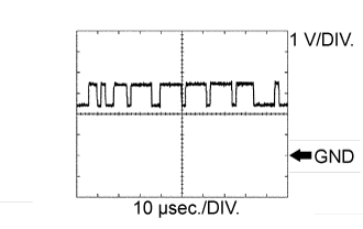
(See waveform 2)WAVEFORM 1
CAN communication signal
Item Content Terminal Name Between R20-5 (CA1P) and R20-10 (GND)
Between R20-6 (CANH) and R20-10 (GND)Tester Range 1 V/DIV., 10 μsec./DIV. Condition Engine switch on (IG) - HINT:
- The waveform varies depending on the CAN communication signal.
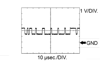
WAVEFORM 2
CAN communication signal
Item Content Terminal Name Between R20-11 (CA1N) and R20-10 (GND)
Between R20-12 (CANL) and R20-10 (GND)Tester Range 1 V/DIV., 10 μsec./DIV. Condition Engine switch on (IG) - HINT:
- The waveform varies depending on the CAN communication signal.
 |
 |
| DRIVING SUPPORT ECU ASSEMBLY |
CHECK DRIVING SUPPORT ECU ASSEMBLY

Terminal No. (Symbol) Wiring Color Terminal Description Condition Specified Condition E164-7 (B) - E164-28 (GND) P - BR Power source Engine switch on (IG) 11 to 14 V E164-8 (CA1P) - E164-28 (GND) W - BR CAN communication signal Engine switch on (IG) Pulse generation
(See waveform 1)E164-9 (CA1N) - E164-28 (GND) P - BR CAN communication signal Engine switch on (IG) Pulse generation
(See waveform 2)E164-10 (CA2H) - E164-28 (GND) L - BR CAN communication signal Engine switch on (IG) Pulse generation
(See waveform 1)E164-11 (CA2L) - E164-28 (GND) B - BR CAN communication signal Engine switch on (IG) Pulse generation
(See waveform 2)E164-23 (SPSW) - E164-28 (GND) W - BR Steering pad switch signal (lane departure alert main switch signal) Engine switch off, lane departure alert main switch off 10 kΩ or higher E164-23 (SPSW) - E164-28 (GND) W - BR Steering pad switch signal (lane departure alert main switch signal) Engine switch off, lane departure alert main switch on 235.2 to 244.8 Ω E164-28 (GND) - Body ground BR - Body ground Ground Always Below 1 Ω WAVEFORM 1
CAN communication signal
Item Content Terminal Name Between E164-8 (CA1P) and E164-28 (GND)
Between E164-10 (CA2H) and E164-28 (GND)Tester Range 1 V/DIV., 10 μsec./DIV. Condition Engine switch on (IG) - HINT:
- The waveform varies depending on the CAN communication signal.
WAVEFORM 2
CAN communication signal
Item Content Terminal Name Between E164-9 (CA1N) and E164-28 (GND)
Between E164-11 (CA2L) and E164-28 (GND)Tester Range 1 V/DIV., 10 μsec./DIV. Condition Engine switch on (IG) - HINT:
- The waveform varies depending on the CAN communication signal.
 |
 |