Dynamic Radar Cruise Control System System Diagram

Engine Hybrid System. Land Cruiser. Urj200, 202 Grj200 Vdj200
Cruise Control. Land Cruiser. Urj200, 202 Grj200 Vdj200

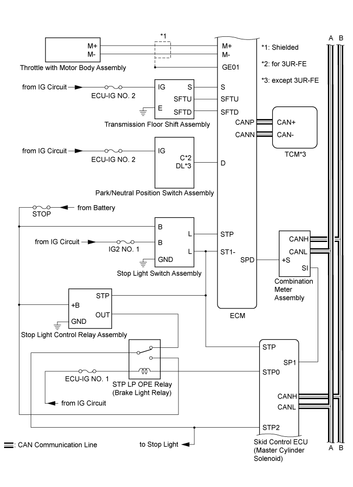
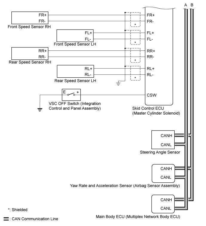
Dynamic Radar Cruise Control System -- System Diagram


Land Cruiser. Urj200, 202 Grj200 Vdj200.Cruise Control.Cruise Control System.Dynamic Radar Cruise Control System  System Diagram


Land Cruiser. Urj200, 202 Grj200 Vdj200.Cruise Control.Cruise Control System.Dynamic Radar Cruise Control System  System Diagram


Land Cruiser. Urj200, 202 Grj200 Vdj200.Cruise Control.Cruise Control System.Dynamic Radar Cruise Control System  System Diagram


Communication Table
Sender
Receiver
Signal
Line
ECM
Driving Support ECU Assembly
  1. Cruise control operation
  2. Accelerator pedal idle position
  3. Accel override operation
  4. Cruise control speed status
  5. Approach warning
  6. Brake signal
  7. Cruise control main switch (ON/OFF) on
  8. Cruise control mode
  9. Set vehicle-to-vehicle distance
  10. Cruise preset vehicle speed
CAN
Skid Control ECU
  1. Cruise control operation
  2. Accelerator pedal idle position
  3. Cruise control operation request
  4. Braking request
  5. Target acceleration from cruise control system
CAN
Combination Meter Assembly
  1. Low speed cancel buzzer request
  2. Low speed zone leading vehicle lost buzzer
  3. Control vehicle speed unit
  4. Cruise control display ID
  5. Cruise control vehicle speed
CAN
Forward Recognition Camera
Cruise control operation
CAN
Driving Support ECU Assembly
ECM
  1. Cruise control target acceleration
  2. Cruise control mode
  3. Target vehicle detection
  4. Vehicle-to-vehicle distance control switch status
  5. Detection of dirt adhesion on millimeter wave radar sensor
  6. Millimeter wave radar sensor malfunction
  7. Approach warning
  8. Bad environment detection
  9. Cruise control target acceleration raw data
  10. Force request for driving support ECU assembly
  11. Control status of driving support ECU assembly
CAN
Combination Meter Assembly
Millimeter wave radar sensor beam axis deviation
CAN
Skid Control ECU
Driving Support ECU Assembly
  1. Stop light switch status
  2. Yaw rate sensor zero point
  3. Yaw rate sensor zero point malfunction
  4. Under brake control
CAN
ECM
  1. Wheel speed
  2. Under TRAC control
  3. Under VSC control
  4. Cruise control cancellation request
  5. Stop light switch control relay malfunction
  6. Temporary inhibition of brake control
  7. Under brake control
  8. Presumed road slope
  9. Estimated acceleration
CAN
Steering Sensor
Driving Support ECU Assembly
  1. Steering sensor malfunction
  2. Steering angle
  3. Steering sensor zero point
CAN
Main Body ECU
Driving Support ECU Assembly
Country specification information
CAN
Airbag Sensor Assembly
Driving Support ECU Assembly
  1. Yaw rate sensor
  2. Yaw rate sensor malfunction
  3. Yaw rate sensor voltage
CAN