Land Cruiser URJ200 URJ202 GRJ200 VDJ200 - 1UR-FE ENGINE CONTROL
CHECK FOR ANY OTHER DTCS OUTPUT (IN ADDITION TO DTC P2121)
READ VALUE USING GTS (ACCELERATOR PEDAL POSITION SENSOR)
REPLACE ACCELERATOR PEDAL POSITION SENSOR ASSEMBLY
CHECK WHETHER DTC OUTPUT RECURS (DTC P2121)
DTC P2121 Throttle / Pedal Position Sensor / Switch "D" Circuit Range / Performance
DESCRIPTION
- HINT:
- Refer to DTC P2120 ().
| DTC No. | DTC Detection Condition | Trouble Area |
| P2121 | Either of following conditions 1 or 2 met for 0.5 seconds (1 trip detection logic) 1. Difference between VPA and VPA2 is less than 0.4 V, or more than 1.2 V. (learned value of accelerator off position) 2. Difference between VPA and VPA2 is greater than or equal to the specified value. |
Accelerator pedal sensor assembly ECM |
MONITOR DESCRIPTION
The accelerator pedal position sensor is mounted on the accelerator pedal bracket. The accelerator pedal position sensor has 2 sensor elements and 2 signal outputs: VPA and VPA2. VPA is used to detect the actual accelerator pedal angle (used for engine control) and VPA2 is used to detect malfunctions in VPA.
When the difference between the output voltages of VPA and VPA2 deviates from the standard, the ECM determines that the accelerator pedal position sensor is malfunctioning. The ECM turns on the MIL and stores the DTC.
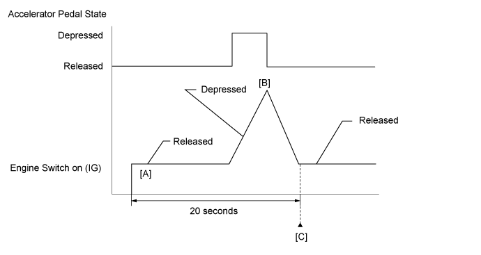
CONFIRMATION DRIVING PATTERN

- HINT:
| GTS Display | Description |
| NORMAL | DTC judgment completed System normal |
| ABNORMAL | DTC judgment completed System abnormal |
| INCOMPLETE | DTC judgment not completed Perform driving pattern after confirming DTC enabling conditions |
| N/A | Unable to perform DTC judgment Number of DTCs which do not fulfill DTC preconditions has reached ECU memory limit |
- HINT:
FAIL-SAFE
The accelerator pedal position sensor has two (main and sub) sensor circuits. If a malfunction occurs in either of the sensor circuits, the ECM detects the abnormal signal voltage difference between the two sensor circuits and switches to limp mode. In limp mode, the functioning circuit is used to calculate the accelerator pedal position to allow the vehicle to continue driving. If both circuits malfunction, the ECM regards the accelerator pedal as being fully released. In this case, the throttle valve remains closed as if the engine is idling.
If a pass condition is detected and then the engine switch is turned off, the fail-safe operation stops and the system returns to normal.
WIRING DIAGRAM
Refer to DTC P2120 ().
INSPECTION PROCEDURE
- HINT:
| 1.CHECK FOR ANY OTHER DTCS OUTPUT (IN ADDITION TO DTC P2121) |
Connect the GTS to the DLC3.
Turn the engine switch on (IG).
Turn the GTS on.
Enter the following menus: Powertrain / Engine and ECT / Trouble codes.
Read DTCs.
| Result | Proceed to |
| P2121 is output | A |
| P2121 and other DTCs are output | B |
- HINT:
- If any DTCs other than P2121 are output, troubleshoot those DTCs first.
|
| ||||
| A | |
| 2.READ VALUE USING GTS (ACCELERATOR PEDAL POSITION SENSOR) |

Connect the GTS to the DLC3.
Turn the engine switch on (IG).
Turn the GTS on.
Enter the following menus: Powertrain / Engine and ECT / Data List / All Data / Accel Sensor Out No. 1 and Accel Sensor Out No. 2.
Read the values displayed on the GTS.
- Standard Voltage:
Accelerator Pedal Operation Accel Sensor Out No. 1 Accel Sensor Out No. 2 Difference between Accel Sensor Out No. 1 and Accel Sensor Out No. 2 Released 0.5 to 1.1 V 1.2 to 2.0 V 0.4 to 1.2 V Depressed 2.6 to 4.5 V 3.4 to 4.75 V
| *a | Depressed |
| *b | Released |
|
| ||||
| OK | ||
| ||
| 3.REPLACE ACCELERATOR PEDAL POSITION SENSOR ASSEMBLY |
Replace the accelerator pedal position sensor assembly ().
| NEXT | |
| 4.CHECK WHETHER DTC OUTPUT RECURS (DTC P2121) |
Connect the GTS to the DLC3.
Turn the engine switch on (IG).
Turn the GTS on.
Clear DTCs ().
Drive the vehicle in accordance with the driving pattern described in Confirmation Driving Pattern.
Read DTCs.
| Result | Proceed to |
| P2121 is output | A |
| No DTC is output | B |
|
| ||||
| A | ||
| ||