Engine Hybrid System. Land Cruiser. Urj200, 202 Grj200 Vdj200
Cruise Control. Land Cruiser. Urj200, 202 Grj200 Vdj200
Cruise Control System -- Terminals Of Ecm |
| CHECK ECM (for 3UR-FE) |

- HINT:
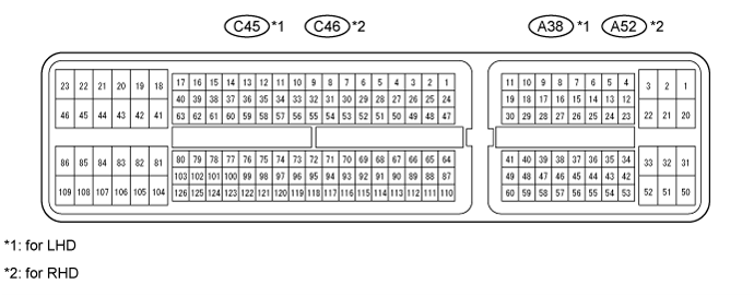
- The standard normal voltage between each pair of ECM terminals is shown in the table below. The appropriate conditions for checking each pair of terminals are also indicated. The result of checks should be compared with the standard normal voltage for that pair of terminals, displayed in the Specified Condition column. The illustration above can be used as a reference to identify the ECM terminal locations.
| Terminal No. (Symbol) | Wiring Color | Terminal Description | Condition | Specified Condition |
| C45-81 (E1) - Body ground | W-B - Body ground | ECM ground | Always | Below 1 Ω |
| C45-49 (D) - Body ground | P - Body ground | D shift position signal | Ignition switch ON Shift lever in D | 11 to 14 V |
| Ignition switch ON Shift lever not in D | Below 1 V | |||
| A38-39 (SFTU) - Body ground | V - Body ground | Up-shift switch signal | Ignition switch ON Shift lever in S | 11 to 14 V |
| Ignition switch ON Shift lever in + | Below 1 V | |||
| A38-27 (S) - Body ground | W - Body ground | S shift position switch signal | Ignition switch ON Shift lever in S | 11 to 14 V |
| Ignition switch ON Shift lever not in S | Below 1 V | |||
| A38-47 (SFTD) - Body ground | L - Body ground | Down-shift switch signal | Ignition switch ON Shift lever in S | 11 to 14 V |
| Ignition switch ON Shift lever in - | Below 1 V | |||
| A38-7 (STP) - Body ground | R - Body ground | Stop light signal | Brake pedal depressed | 7.5 to 14 V |
| Brake pedal released | 0 to 1.5 V | |||
| A38-8 (ST1-) - Body ground | P - Body ground | Stop light signal (opposite to STP terminal) | Ignition switch ON Brake pedal depressed | 0 to 1.5 V |
| Ignition switch ON Brake pedal released | 7.5 to 14 V | |||
| A38-60 (CCS) - A38-59 (ECCS) | L - BR | Cruise control main switch signal | Ignition switch ON Main switch off | 1 MΩ or higher |
| Ignition switch ON CANCEL switch held on | 1510 to 1570 Ω | |||
| Ignition switch ON -SET switch held on | 620 to 640 Ω | |||
| Ignition switch ON +RES switch held on | 235 to 245 Ω | |||
| Ignition switch ON Main switch on | Below 2.5 Ω |
| CHECK ECM (for 1UR-FE) |

- HINT:
- The standard normal voltage between each pair of ECM terminals is shown in the table below. The appropriate conditions for checking each pair of terminals are also indicated. The result of checks should be compared with the standard normal voltage for that pair of terminals, displayed in the Specified Condition column. The illustration above can be used as a reference to identify the ECM terminal locations.
| Terminal No. (Symbol) | Wiring Color | Terminal Description | Condition | Specified Condition |
| C45*1-81 (E1) - Body ground C46*2-81 (E1) - Body ground | BR - Body ground | ECM ground | Always | Below 1 Ω |
| C45*1-27 (D) - Body ground C46*2-27 (D) - Body ground | Y - Body ground | D shift position signal | Ignition switch ON Shift lever in D | 11 to 14 V |
| Ignition switch ON Shift lever not in D | Below 1 V | |||
| A38*1-38 (SFTU) - Body ground A52*2-38 (SFTU) - Body ground | V - Body ground | Up-shift switch signal | Ignition switch ON Shift lever in S | 11 to 14 V |
| Ignition switch ON Shift lever in "+" | Below 1 V | |||
| A38*1-25 (S) - Body ground A52*2-25 (S) - Body ground | W - Body ground | S shift position switch signal | Ignition switch ON Shift lever in S | 11 to 14 V |
| Ignition switch ON Shift lever not in S | Below 1 V | |||
| A38*1-27 (SFTD) - Body ground A52*2-27 (SFTD) - Body ground | L - Body ground | Down-shift switch signal | Ignition switch ON Shift lever in S | 11 to 14 V |
| Ignition switch ON Shift lever in "-" | Below 1 V | |||
| A38*1-36 (STP) - Body ground A52*2-36 (STP) - Body ground | R - Body ground | Stop light signal | Brake pedal depressed | 7.5 to 14 V |
| Brake pedal released | 0 to 1.5 V | |||
| A38*1-35 (ST1-) - Body ground A52*2-35 (ST1-) - Body ground | P - Body ground | Stop light signal (opposite to STP terminal) | Ignition switch ON Brake pedal depressed | 0 to 1.5 V |
| Ignition switch ON Brake pedal released | 7.5 to 14 V | |||
| A38*1-45 (CCS) - Body ground A52*2-45 (CCS) - Body ground | L - Body ground | Cruise control main switch signal | Ignition switch ON Main switch off | 1 MΩ or higher |
| Ignition switch ON CANCEL switch held on | 1510 to 1570 Ω | |||
| Ignition switch ON -SET switch held on | 620 to 640 Ω | |||
| Ignition switch ON +RES switch held on | 235 to 245 Ω | |||
| Ignition switch ON Main switch on | Below 2.5 Ω |
- *1: for LHD
- *2: for RHD
| CHECK ECM (for 1GR-FE) |

- HINT:
- The standard voltage between each pair of ECM terminals is shown in the table below. The appropriate conditions for checking each pair of terminals are also indicated. The result of checks should be compared with the standard voltage for that pair of terminals, which is displayed in the "Specified Condition" column. The illustration above can be used as a reference to identify the ECM terminal locations.
| Terminal No. (Symbol) | Wiring Color | Terminal Description | Condition | Specified Condition |
| C45*1-81 (E1) - Body ground C46*2-81 (E1) - Body ground | BR - Body ground | ECM ground | Always | Below 1 Ω |
| C45*1-27 (D) - Body ground C46*2-27 (D) - Body ground | P - Body ground | D shift position signal*3 | Ignition switch ON Shift lever in D | 11 to 14 V |
| Ignition switch ON Shift lever not in D | Below 1 V | |||
| C45*1-27 (D) - Body ground C46*2-27 (D) - Body ground | P - Body ground | Clutch switch signal*4 | Ignition switch ON clutch pedal depressed | Below 1 V |
| Ignition switch ON clutch pedal released | 11 to 14 V | |||
| A38*1-38 (SFTU) - Body ground | V - Body ground | Up-shift switch signal*3 | Ignition switch ON Shift lever in S | 11 to 14 V |
| Ignition switch ON Shift lever in "+" | Below 1 V | |||
| A38*1-25 (S) - Body ground | W - Body ground | S shift position switch signal*3 | Ignition switch ON Shift lever in S | 11 to 14 V |
| Ignition switch ON Shift lever not in S | Below 1 V | |||
| A38*1-27 (SFTD) - Body ground | L - Body ground | Down-shift switch signal*3 | Ignition switch ON Shift lever in S | 11 to 14 V |
| Shift lever in "-" | Below 1 V | |||
| A38*1-36 (STP) - Body ground A52*2-36 (STP) - Body ground | R - Body ground | Stop light signal | Brake pedal depressed | 7.5 to 14 V |
| Ignition switch ON Brake pedal released | 0 to 1.5 V | |||
| A38*1-35 (ST1-) - Body ground A52*2-35 (ST1-) - Body ground | P - Body ground | Stop light signal (opposite to STP terminal) | Ignition switch ON Brake pedal depressed | 0 to 1.5 V |
| Ignition switch ON Brake pedal released | 7.5 to 14 V | |||
| A38*1-45 (CCS) - Body ground A52*2-45 (CCS) - Body ground | L - Body ground | Cruise control main switch signal | Ignition switch ON Main switch off | 1 MΩ or higher |
| Ignition switch ON CANCEL switch held on | 1510 to 1570 Ω | |||
| Ignition switch ON -SET switch held on | 620 to 640 Ω | |||
| Ignition switch ON +RES switch held on | 235 to 245 Ω | |||
| Ignition switch ON Main switch on | Below 2.5 Ω |
- *1: for LHD
- *2: for RHD
- *3: for Automatic Transmission
- *4: for Manual Transmission
| CHECK ECM (for 1VD-FTV (w/ DPF)) |
- HINT:
- The standard normal voltage between each pair of ECM terminals is shown in the table below. The appropriate conditions for checking each pair of terminals are also indicated. The result of the checks should be compared with the standard normal voltage for that pair of terminals, which is displayed in the Specified Condition column. The illustration above can be used as a reference to identify the ECM terminal locations.
| Terminal No. (Symbol) | Wiring Color | Terminal Description | Condition | Specified Condition |
| C45*1-81 (E1) - Body ground C46*2-81 (E1) - Body ground | BR - Body ground | ECM ground | Always | Below 1 Ω |
| C45*1-28 (D) - Body ground C46*2-28 (D) - Body ground | P - Body ground | D shift position signal | Ignition switch ON Shift lever in D | 11 to 14 V |
| Ignition switch ON Shift lever not in D | Below 1 V | |||
| A38*1-38 (SFTU) - Body ground A52*2-38 (SFTU) - Body ground | V - Body ground | Up-shift switch signal | Ignition switch ON Shift lever in S | 11 to 14 V |
| Ignition switch ON Shift lever in "+" | Below 1 V | |||
| A38*1-25 (S) - Body ground A52*2-25 (S) - Body ground | W - Body ground | S shift position switch signal | Ignition switch ON Shift lever in S | 11 to 14 V |
| Ignition switch ON Shift lever not in S | Below 1 V | |||
| A38*1-37 (SFTD) - Body ground A52*2-37 (SFTD) - Body ground | L - Body ground | Down-shift switch signal | Ignition switch ON Shift lever in S | 11 to 14 V |
| Ignition switch ON Shift lever in "-" | Below 1 V | |||
| A38*1-13 (STP) - Body ground A52*2-13 (STP) - Body ground | R - Body ground | Stop light signal | Brake pedal depressed | 7.5 to 14 V |
| Brake pedal released | 0 to 1.5 V | |||
| A38*1-35 (ST1-) - Body ground A52*2-35 (ST1-) - Body ground | P - Body ground | Stop light signal (opposite to STP terminal) | Ignition switch ON Brake pedal depressed | 0 to 1.5 V |
| Ignition switch ON Brake pedal released | 7.5 to 14 V | |||
| A38*1-40 (CCS) - Body ground A52*2-40 (CCS) - Body ground | L - Body ground | Cruise control main switch signal | Ignition switch ON Main switch off | 1 MΩ or higher |
| Ignition switch ON CANCEL switch held on | 1510 to 1570 Ω | |||
| Ignition switch ON -SET switch hed on | 620 to 640 Ω | |||
| Ignition switch ON +RES switch held on | 235 to 245 Ω | |||
| Ignition switch ON Main switch on | Below 2.5 Ω |
- *1: for LHD
- *2: for RHD
| CHECK ECM (for 1VD-FTV (w/o DPF)) |

- HINT:
- The standard normal voltage between each pair of ECM terminals is shown in the table below. The appropriate conditions for checking each pair of terminals are also indicated. The result of the checks should be compared with the standard normal voltage for that pair of terminals, which is displayed in the Specified Condition column. The illustration above can be used as a reference to identify the ECM terminal locations.
| Terminal No. (Symbol) | Wiring Color | Terminal Description | Condition | Specified Condition |
| C45*1-81 (E1) - Body ground C46*2-81 (E1) - Body ground | BR - Body ground | ECM ground | Always | Below 1 Ω |
| C45*1-28 (D) - Body ground C46*2-28 (D) - Body ground | P - Body ground | D shift position signal*3 | Ignition switch ON Shift lever in D | 11 to 14 V |
| Ignition switch ON Shift lever not in D | Below 1 V | |||
| A38*1-42 (CLSW) - Body ground C46*2-28 (CLSW) - Body ground | B - Body ground | Clutch switch signal*4 | Ignition switch ON Clutch pedal depressed | Below 1 V |
| Ignition switch ON Clutch pedal released | 11 to 14 V | |||
| A38*1-38 (SFTU) - Body ground A52*2-38 (SFTU) - Body ground | V - Body ground | Up-shift switch signal*3 | Ignition switch ON Shift lever in S | 11 to 14 V |
| Ignition switch ON Shift lever in "+" | Below 1 V | |||
| A38*1-25 (S) - Body ground A52*2-25 (S) - Body ground | W - Body ground | S shift position switch signal | Ignition switch ON Shift lever in S | 11 to 14 V |
| Ignition switch ON Shift lever not in S | Below 1 V | |||
| A38*1-37 (SFTD) - Body ground A52*2-37 (SFTD) - Body ground | L - Body ground | Down-shift switch signal | Ignition switch ON Shift lever in S | 11 to 14 V |
| Ignition switch ON Shift lever in "-" | Below 1 V | |||
| A38*1-13 (STP) - Body ground A52*2-13 (STP) - Body ground | R - Body ground | Stop light signal | Brake pedal depressed | 7.5 to 14 V |
| Brake pedal released | 0 to 1.5 V | |||
| A38*1-35 (ST1-) - Body ground A52*2-35 (ST1-) - Body ground | P - Body ground | Stop light signal (opposite to STP terminal) | Ignition switch ON Brake pedal depressed | 0 to 1.5 V |
| Ignition switch ON Brake pedal released | 7.5 to 14 V | |||
| A38*1-40 (CCS) - Body ground A52*2-40 (CCS) - Body ground | L - Body ground | Cruise control main switch signal | Ignition switch ON Main switch off | 1 MΩ or higher |
| Ignition switch ON CANCEL switch held on | 1510 to 1570 Ω | |||
| Ignition switch ON -SET switch hed on | 620 to 640 Ω | |||
| Ignition switch ON +RES switch held on | 235 to 245 Ω | |||
| Ignition switch ON Main switch on | Below 2.5 Ω |
- *1: for LHD
- *2: for RHD
- *3: for Automatic Transmission
- *4: for Manual Transmission