Fuel Cooler (For Engine Room Side) Installation
CONNECT NO. 7 WATER BY-PASS HOSE
INSTALL FUEL COOLER ASSEMBLY
CONNECT NO. 3 FUEL HOSE
CONNECT NO. 6 WATER BY-PASS HOSE
INSTALL NO. 4 NOZZLE LEAKAGE PIPE
INSTALL NO. 3 NOZZLE LEAKAGE PIPE
INSTALL EGR COOLER INSULATOR (w/ EGR System)
INSTALL EGR VALVE ASSEMBLY WITH EGR COOLER (w/ EGR System)
INSTALL EGR PIPE INSULATOR (w/ EGR System)
INSTALL INTAKE MANIFOLD INSULATOR (w/ EGR System)
INSTALL NO. 3 INTAKE MANIFOLD
CONNECT NO. 2 ENGINE WIRE
INSTALL INTAKE PIPE
INSTALL NO. 2 INTAKE MANIFOLD INSULATOR (w/ Intercooler)
INSTALL NO. 1 INTAKE MANIFOLD INSULATOR (w/ Intercooler)
INSTALL COMMON RAIL ASSEMBLY LH AND RH
Fuel Cooler (For Engine Room Side) -- Installation |
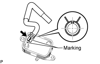
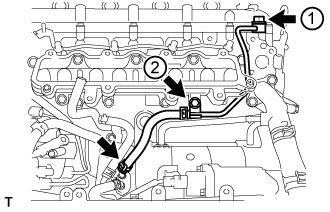
| 1. CONNECT NO. 7 WATER BY-PASS HOSE |
Connect the water by-pass hose to the fuel cooler.
- HINT:
- Align the alignment marks and connect the hose.
- Align the pinching portion of the clamp with the hose alignment mark and connect the hose.
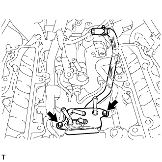
| 2. INSTALL FUEL COOLER ASSEMBLY |
Install the fuel cooler with the 2 bolts.
- Torque:
- 10 N*m{102 kgf*cm, 7 ft.*lbf}
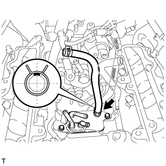
| 3. CONNECT NO. 3 FUEL HOSE |
Connect the fuel hose to the fuel cooler.
- HINT:
- Align the alignment marks and connect the hose.
- Align the pinching portion of the clamp with the hose alignment mark and connect the hose.
| 4. CONNECT NO. 6 WATER BY-PASS HOSE |
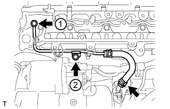
| 5. INSTALL NO. 4 NOZZLE LEAKAGE PIPE |
Temporarily install a new gasket and the No. 4 nozzle leakage pipe with the union bolt and bolt.
Tighten the union bolt and bolt in the order shown in the illustration.
- Torque:
- for union bolt:
- 21 N*m{214 kgf*cm, 15 ft.*lbf}
- for bolt:
- 10 N*m{102 kgf*cm, 7 ft.*lbf}
Connect the No. 2 fuel hose to the fuel cooler.
| 6. INSTALL NO. 3 NOZZLE LEAKAGE PIPE |
Temporarily install a new gasket and the No. 3 nozzle leakage pipe with the union bolt and bolt.
Tighten the union bolt and bolt in the order shown in the illustration.
- Torque:
- for union bolt:
- 21 N*m{214 kgf*cm, 15 ft.*lbf}
- for bolt:
- 10 N*m{102 kgf*cm, 7 ft.*lbf}
Connect the No. 1 fuel hose to the fuel cooler.
| 7. INSTALL EGR COOLER INSULATOR (w/ EGR System) |
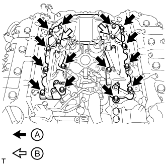
| 8. INSTALL EGR VALVE ASSEMBLY WITH EGR COOLER (w/ EGR System) |
Connect the No. 5 water by-pass hose to the water by-pass outlet.
Install 2 new gaskets and the EGR valve with EGR cooler with the 6 bolts labeled A and 4 bolts labeled B shown in the illustration.
- Torque:
- for bolt A:
- 21 N*m{214 kgf*cm, 15 ft.*lbf}
- for bolt B:
- 29 N*m{296 kgf*cm, 21 ft.*lbf}
- HINT:
- The gasket claws should face toward the No. 1 and No. 2 EGR pipes.
| 9. INSTALL EGR PIPE INSULATOR (w/ EGR System) |
Install the EGR pipe insulator with the 2 bolts.
- Torque:
- 21 N*m{214 kgf*cm, 15 ft.*lbf}
- NOTICE:
- If the No. 1 and No. 2 EGR pipe insulator installation stay is deformed, or the bolt holes of the EGR pipe insulator do not align, replace the No. 1 and No. 2 EGR pipes as a set.
| 10. INSTALL INTAKE MANIFOLD INSULATOR (w/ EGR System) |
| 11. INSTALL NO. 3 INTAKE MANIFOLD |
Install 2 new gaskets to the No. 1 and No. 2 intake manifolds.
Install the No. 3 intake manifold with the 16 bolts.
- Torque:
- 21 N*m{214 kgf*cm, 15 ft.*lbf}
Bolt LengthItem
| Length
|
Bolt A
| 25 mm (0.984 in.)
|
Bolt B
| 70 mm (2.76 in.)
|
| 12. CONNECT NO. 2 ENGINE WIRE |
Connect the No. 2 engine wire with the 3 bolts.
- Torque:
- for bolt A:
- 13 N*m{133 kgf*cm, 10 ft.*lbf}
- for bolt B:
- 32 N*m{326 kgf*cm, 24 ft.*lbf}
Attach the 2 wire harness clamps.
w/ EGR System:
Install 2 new gaskets and the intake pipe with the 6 bolts and 2 nuts.
- Torque:
- 21 N*m{214 kgf*cm, 15 ft.*lbf}
w/o EGR System:
Install a new gasket and the intake pipe with the 4 bolts and 2 nuts.
- Torque:
- 21 N*m{214 kgf*cm, 15 ft.*lbf}
| 14. INSTALL NO. 2 INTAKE MANIFOLD INSULATOR (w/ Intercooler) |
| 15. INSTALL NO. 1 INTAKE MANIFOLD INSULATOR (w/ Intercooler) |
| 16. INSTALL COMMON RAIL ASSEMBLY LH AND RH |
(Click here)