Cylinder Head -- Replacement |
| 1. REPLACE INTAKE VALVE GUIDE BUSH |
Heat the cylinder head to approximately 80 to 100°C (176 to 212°F).
Place the cylinder head on wooden blocks.
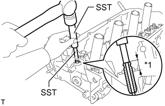
Using SST and a hammer, tap out the intake valve guide bush.
- SST
- 09201-10000(09201-01050)
09950-70010(09951-07100)
 |
Using a caliper gauge, measure the bush bore diameter of the cylinder head.
- Standard Bush Bore Diameter:
Item Specified Condition STD 10.285 to 10.306 mm (0.4049 to 0.4057 in.) O/S 0.05 10.335 to 10.356 mm (0.4069 to 0.4077 in.)
Select a new valve guide bush.
- New Guide Bush:
Item Specified Condition Bush Bore Diameter 10.285 to 10.306 mm (0.4049 to 0.4057 in.) 10.335 to 10.356 mm (0.4069 to 0.4077 in.) Bush to be Used STD O/S 0.05
If the bush bore diameter of the cylinder head is more than 10.356 mm (0.408 in.), replace the cylinder head sub-assembly.- New Guide Bush Diameter:
Item Bush Diameter STD 10.333 to 10.344 mm (0.4068 to 0.4072 in.) O/S 0.05 10.383 to 10.394 mm (0.4088 to 0.4092 in.)
- HINT:
- Standard bush length: 41.3 to 41.7 mm (1.63 to 1.64 in.)
Using SST and a hammer, tap in a new intake valve guide bush to the standard protrusion height.
- SST
- 09201-10000(09201-01050)
09950-70010(09951-07100)
- Standard protrusion height:
- 14.3 to 14.7 mm (0.563 to 0.579 in.)
Text in Illustration *1 Protrusion Height
 |
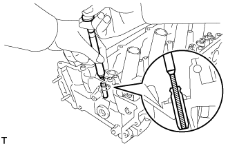
Using a sharp 5.5 mm reamer, ream the guide bush to obtain the standard oil clearance between the intake valve guide bush and intake valve stem.
- Standard oil clearance:
- 0.025 to 0.060 mm (0.000984 to 0.00236 in.)
 |
| 2. REPLACE EXHAUST VALVE GUIDE BUSH |
Heat the cylinder head to approximately 80 to 100°C (176 to 212°F).
Place the cylinder head on wooden blocks.
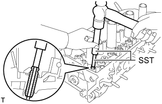
Using SST and a hammer, tap out the exhaust valve guide bush.
- SST
- 09201-10000(09201-01050)
09950-70010(09951-07100)
 |
Using a caliper gauge, measure the bush bore diameter of the cylinder head.
- Standard Bush Bore Diameter:
Item Specified Condition STD 10.285 to 10.306 mm (0.4049 to 0.4057 in.) O/S 0.05 10.335 to 10.356 mm (0.4069 to 0.4077 in.)
Select a new exhaust valve guide bush.
- New Guide Bush:
Item Specified Condition Bush Bore Diameter 10.285 to 10.306 mm (0.4049 to 0.4057 in.) 10.335 to 10.356 mm (0.4069 to 0.4077 in.) Bush to be Used STD O/S 0.05
If the bush bore diameter of the cylinder head is more than 10.356 mm (0.408 in.), replace the cylinder head sub-assembly.- New Guide Bush Diameter:
Item Bush Diameter STD 10.333 to 10.344 mm (0.4068 to 0.4072 in.) O/S 0.05 10.383 to 10.394 mm (0.4088 to 0.4092 in.)
- HINT:
- Standard bush length: 46.8 to 47.2 mm (1.84 to 1.86 in.)
Using SST and a hammer, tap in a new exhaust valve guide bush to the standard protrusion height.
- SST
- 09201-10000(09201-01050)
09950-70010(09951-07100)
- Standard protrusion height:
- 14.3 to 14.7 mm (0.563 to 0.579 in.)
Text in Illustration *1 Protrusion Height
 |
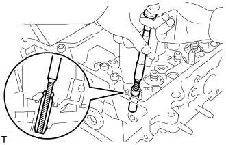
Using a sharp 5.5 mm reamer, ream the exhaust valve guide bush to obtain the standard oil clearance between the exhaust valve guide bush and exhaust valve stem.
- Standard oil clearance:
- 0.030 to 0.065 mm (0.00118 to 0.00256 in.)
 |
| 3. REPLACE SPARK PLUG TUBE |
- HINT:
- When using a new cylinder head, the spark plug tubes must be replaced.
Apply adhesive to the end of a new spark plug tube.
- Adhesive:
- Toyota Genuine Adhesive 1324, Three Bond 1324 or equivalent.
- Standard seal diameter:
- 15 mm (0.591 in.)
Text in Illustration *1 Adhesive - NOTICE:
- Install the spark plug tube within 3 minutes after applying adhesive.
- Be careful not to deform the spark plug tube.
- Be careful not to expose the seal to coolant for at least 1 hour after installing the spark plug tube.
 |
Using a wooden block and hammer, tap in the spark plug tube to the specified protrusion height.
- Standard protrusion height:
- 75.1 to 76.1 mm (2.96 to 3.00 in.)
Text in Illustration *1 Cylinder Head Top Surface *2 Protrusion Height - NOTICE:
- To avoid tapping in the spark plug tube too far, measure the protrusion height while tapping in the tube.
 |
| 4. REPLACE RING PIN |
- NOTICE:
- It is not necessary to remove a ring pin unless it is being replaced.
Remove the ring pins.
Using a plastic-faced hammer, tap in new ring pins to the cylinder head.

Text in Illustration *A for Bank 1 *B for Bank 2 *1 Width *2 Height *3 Protrusion Height - - - Standard Ring Pin:
Item Height Width Protrusion Ring pin A 11 mm (0.433 in.) 11 mm (0.433 in.) 5.5 to 6.5 mm (0.217 to 0.256 in.) Ring pin B 10 mm (0.394 in.) 11 mm (0.433 in.) 3.5 to 6.5 mm (0.138 to 0.256 in.)