Ecd System (W/ Dpf) Active Control Engine Mount System
DESCRIPTION
WIRING DIAGRAM
INSPECTION PROCEDURE
PERFORM ACTIVE TEST USING GTS
CHECK VACUUM
INSPECT VSV FOR ENGINE MOUNT
CHECK HARNESS AND CONNECTOR (VSV FOR ENGINE MOUNT - ECM, EFI NO. 2 FUSE - VSV FOR ENGINE MOUNT)
INSPECT ENGINE MOUNTING INSULATOR FRONT
ECD SYSTEM (w/ DPF) - Active Control Engine Mount System |
DESCRIPTION
The Active Control Engine Mount (ACM) system decreases engine vibration at low engine speed using the VSV for engine mount. The VSV is controlled by a pulse signal transmitted to the VSV from the ECM. The frequency of this pulse signal is matched to the engine speed to decrease engine vibration.
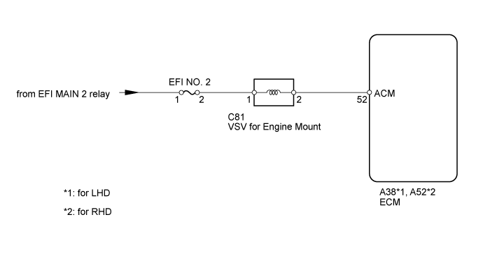
WIRING DIAGRAM
INSPECTION PROCEDURE
- NOTICE:
- Inspect the fuses of circuits related to this system before performing the following inspection procedure.
- After replacing the ECM, the new ECM needs registration (Click here) and initialization (Click here).
| 1.PERFORM ACTIVE TEST USING GTS |
Warm up the engine.
Connect the GTS to the DLC3.
Move the shift lever to N or P.
Enter the following menus: Powertrain / Engine and ECT / Active Test / Control the ACM Inhibit.
Hold the top part of the steering wheel, and turn the Active Test from OFF to ON. Check the engine vibration.
- Result:
Engine Vibration
| Proceed to
|
Increases
| A
|
Does not increase
| B
|
Check if the vacuum hose cap is missing, if the hose is damaged, and if the air and vacuum hoses have looseness, disconnection or blockage.
- OK:
- Vacuum hose cap is not missing and hoses are normal.
| 3.INSPECT VSV FOR ENGINE MOUNT |
Inspect the VSV for engine mount (Click here).
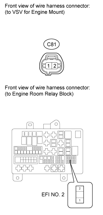
| 4.CHECK HARNESS AND CONNECTOR (VSV FOR ENGINE MOUNT - ECM, EFI NO. 2 FUSE - VSV FOR ENGINE MOUNT) |
Disconnect the VSV for engine mount connector.
Disconnect the ECM connector.
Measure the resistance according to the value(s) in the table below.
- Standard Resistance:
for LHDTester Connection
| Condition
| Specified Condition
|
C81-2 - A38-52 (ACM)
| Always
| Below 1 Ω
|
C81-2 or A38-52 (ACM) - Body ground
| Always
| 10 kΩ or higher
|
for RHDTester Connection
| Condition
| Specified Condition
|
C81-2 - A52-52 (ACM)
| Always
| Below 1 Ω
|
C81-2 or A52-52 (ACM) - Body ground
| Always
| 10 kΩ or higher
|
Remove the EFI NO. 2 fuse from the engine room relay block.
Measure the resistance according to the value(s) in the table below.
- Standard Resistance:
Tester Connection
| Condition
| Specified Condition
|
EFI NO. 2 fuse (2) - C81-1
| Always
| Below 1 Ω
|
| | REPAIR OR REPLACE HARNESS OR CONNECTOR |
|
|
| 5.INSPECT ENGINE MOUNTING INSULATOR FRONT |
Inspect the engine mounting insulator front (Click here).
| | REPLACE ENGINE MOUNTING INSULATOR FRONT (Click here) |
|
|